Method and apparatus for pressure testing a pipe joint

Inactive Publication Date: 2013-08-22
MARICAP OY
View PDF8 Cites 2 Cited by
  • Summary
  • Abstract
  • Description
  • Claims
  • Application Information

AI Technical Summary

Benefits of technology

[0009]The solution according to the invention has a number of important advantages. With the method and apparatus according to the invention it is possible to quickly and easily pressure test and test the tightness of sections, more particularly the points of connection, of piping.
[0010]Consumption of the pressure medium needed is minimal in relation to if the whole pipeline were filled with pressure medium. By using a pressure-medium operated, preferably flexible, bellows means as a sealing means for the first wall part and/or the second wall part, which bellows means when pressurized expands from a first position to a second position in the radial direction and becomes tighter to the inner surface of the pipe, an inexpensive and extremely effective solution is achieved for separating and sealing a pipe section to be tested or pressure tested. By using pressure-medium channels arranged in the body of the device for bringing the pressure medium to the bellows means that function as sealing means, into the chambers of said bellows means, a well-protected and extremely effective solution is achieved for moving the sealing means. By additionally arranging hose means, with which pressure medium is brought to the device, a transfer solution for pressure medium is achieved that is extremely well suited to installation conditions and testing c

Problems solved by technology

The type of joint described has the problem, particularly when applied in the joints of the transfer pipings of pneumatic waste-transporting systems, that a gap or sill that is detrimental to the transportation of material can remain between the pipe parts to be connected.
In prior-art solutions the bushing can contain a countersurface against which the pipe parts to be connected together should be placed, but in practical installation conditions installation errors that result in an unsatisfactory joint can remain in the placement of the pipes into the bushing.
The verification of the tightness o

Method used


Image

  • Method and apparatus for pressure testing a pipe joint
  • Method and apparatus for pressure testing a pipe joint
  • Method and apparatus for pressure testing a pipe joint

Examples


Embodiment Construction

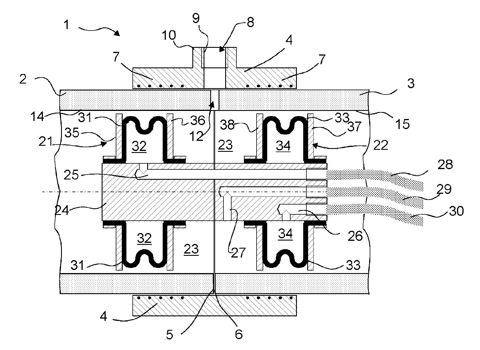
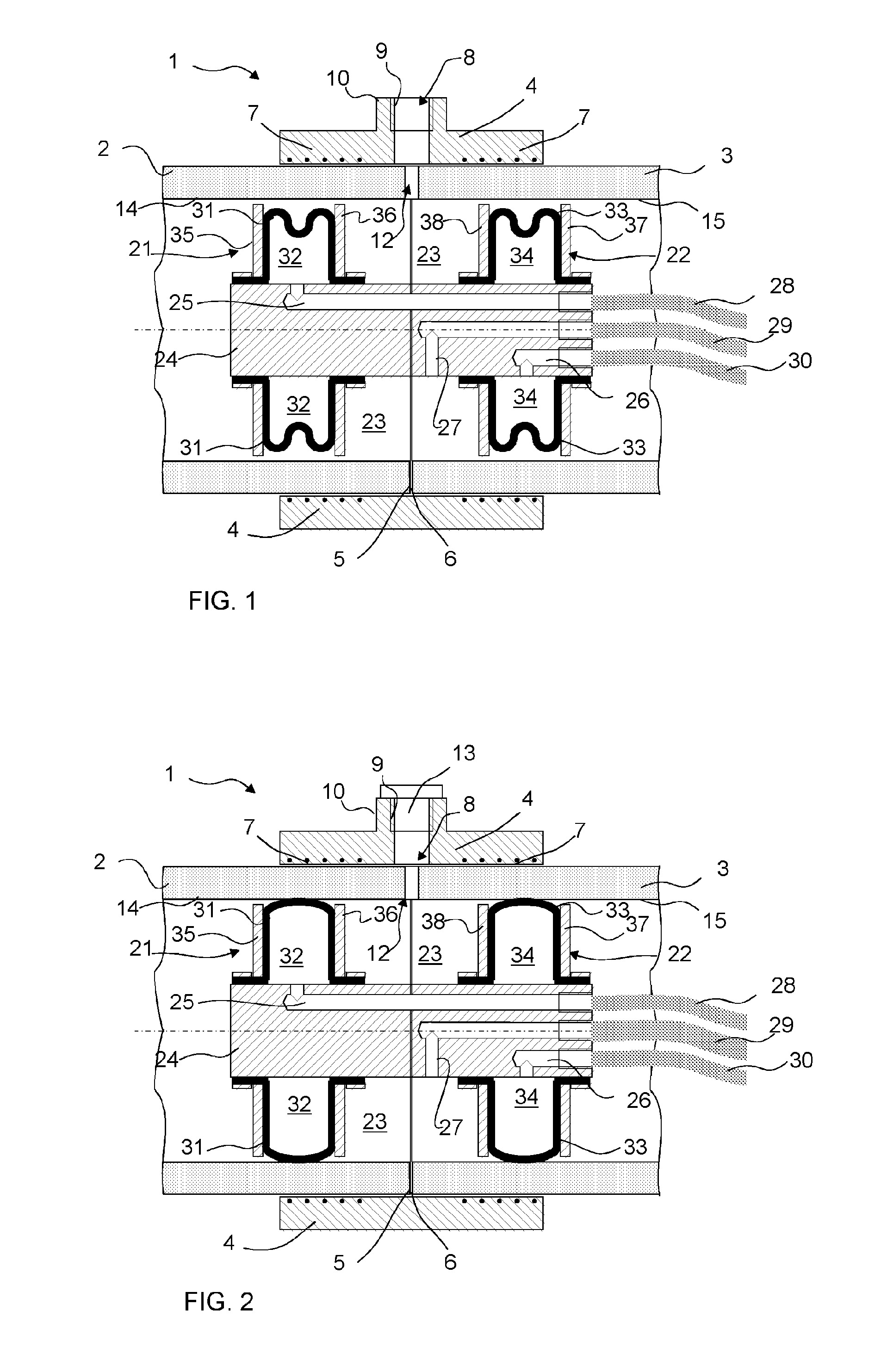
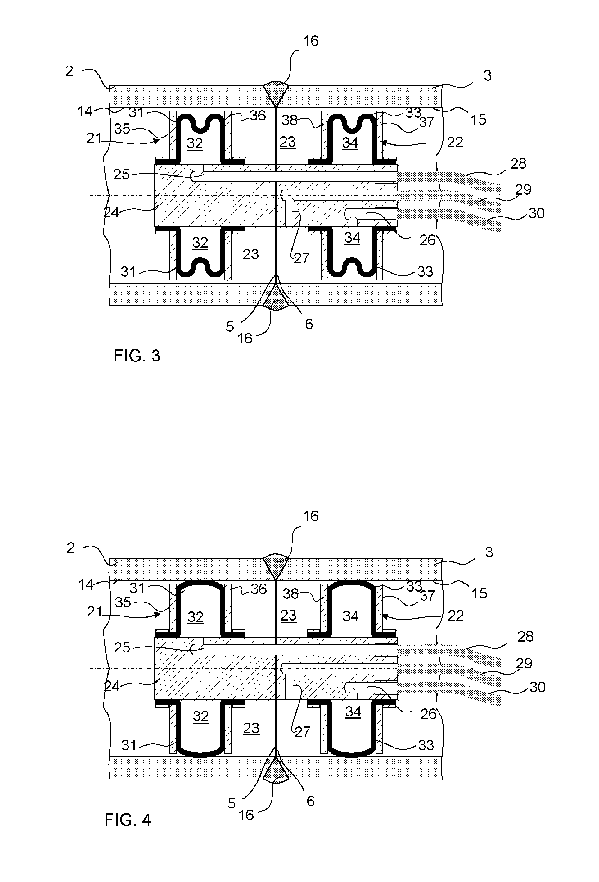
[0016]FIGS. 1 and 2 present a sectioned part of a pipe joint 1 applying a sleeve part 4. In the joint two pipe parts 2 and 3 are connected together end-on-end, in which case the butt end 5 of the first pipe part 2 is against the butt end 6 of the second pipe part 3. The butt end sections of the pipe parts 2, 3 are arranged into the bushing, i.e. into the sleeve part 4. The sleeve part 4 comprises heating means 7, such as thermal resistance wires 7, which warm up when electric current is conducted into them. Connection points (not presented) that are per se prior art can be arranged in the sleeve part 4, which connection points are connected to thermal resistance wires and to which connection points electric current is connected. As a consequence of the heating of the heating means 7, typically resistance wires, a joint forms between the sleeve part 4 and the pipe parts 2, 3 in a manner that is per se known in the art. In the joining of thermoplastic pipes this is, per se, prior art....


PUM

PropertyMeasurementUnit
Pressureaaaaaaaaaa
Distanceaaaaaaaaaa

Abstract

Method for testing and/or for pressure testing the tightness of the joints of the transfer piping of a pneumatic pipe transport system for waste, in which method the pipe section to be tested is separated inside the pipe from the other piping and pressure medium is conducted into the section, and leaks and/or the pressure of the pressure medium are monitored on the section of pipe to be tested. In the method a device is taken inside the piping, which device comprises a first wall part (21), which comprises first sealing means (31), and a second wall part (22), which comprises second sealing means (33), in which case the pipe section to be tested, more particularly the point of connection, remains between the first wall part (21) and the second wall part (22), in which case the sealing means (31) of the first wall part are brought to be tighter to the inside surface (14) of the pipe and the sealing means (33) of the second wall part (22) are brought to be tighter to the inside surface (15) of the pipe, and pressure medium is brought into the chamber space (23) bounded by the first wall part (21) and the second wall part (22) as well as by the inside surface of the pipe section, and the pressure or a change of pressure is measured or a possible sealing defect of the pipe section is otherwise indicated.

Description

BACKGROUND OF THE INVENTION[0001]The object of the invention is a method as defined in the preamble of claim 1.[0002]The object of the invention is also an apparatus according to claim 7.[0003]Bushing joints are generally used for connecting pipes, more particularly plastic pipes, together end-on-end. The point of connection is placed into the bushing, i.e. into the sleeve part, such that the ends of the pipe parts to be connected together are inside the bushing and the bushing is thus around the point of connection extending some distance in the longitudinal direction of the pipes from the point of connection in both directions. The bushing part is provided with thermal resistors or corresponding, in which case when forming the joint electric current is conducted to the resistors, in which case the resistors heat up and a joint forms between the sleeve part and the pipe parts. The type of joint described has the problem, particularly when applied in the joints of the transfer pipin...

Claims


Application Information

Patent Timeline
IPC IPC(8): G01M3/28
CPCB29C65/02B29C66/9121B29C65/8246B29C66/1142B29C66/5221B29C66/5229B29C66/73921B29C66/97F16L47/03G01M3/005G01M3/2853B29C65/3476F16L2101/30B29C65/3432B29C65/7802B29C66/1122B65F5/005G01M3/2815G01M3/28B65F5/00
Inventor SUNDHOLM, GORAN
Owner MARICAP OY
Why Eureka
Try Eureka