Luminescent solar concentrator apparatus, method and applications

Inactive Publication Date: 2013-08-22
ABENGOA SOLAR
View PDF4 Cites 7 Cited by
  • Summary
  • Abstract
  • Description
  • Claims
  • Application Information

AI Technical Summary

Benefits of technology

[0009]Embodiments include a plurality of luminescent solar concentrator apparatuses and a related method for fabricating the plurality of luminescent solar concentrator apparatuses. Most generally, the luminescent solar concentrator apparatuses in accordance with the embodiments include a photovoltaic material layer and a luminescent material layer located over a transparent substrate, where the luminescent material layer is not within an incoming optical pathway through the transparent substrate to the photovoltaic material layer. More specific embodiments of the luminescent solar concentrator apparatuses in accordance with the embodiments comprise a photovoltaic material layer located at least partially embedded with

Problems solved by technology

Nonetheless, light that is lost through the x, y surfaces or reabsorbed by the luminescent material, or otherwise not inc

Method used


Image

  • Luminescent solar concentrator apparatus, method and applications
  • Luminescent solar concentrator apparatus, method and applications
  • Luminescent solar concentrator apparatus, method and applications

Examples


first embodiment

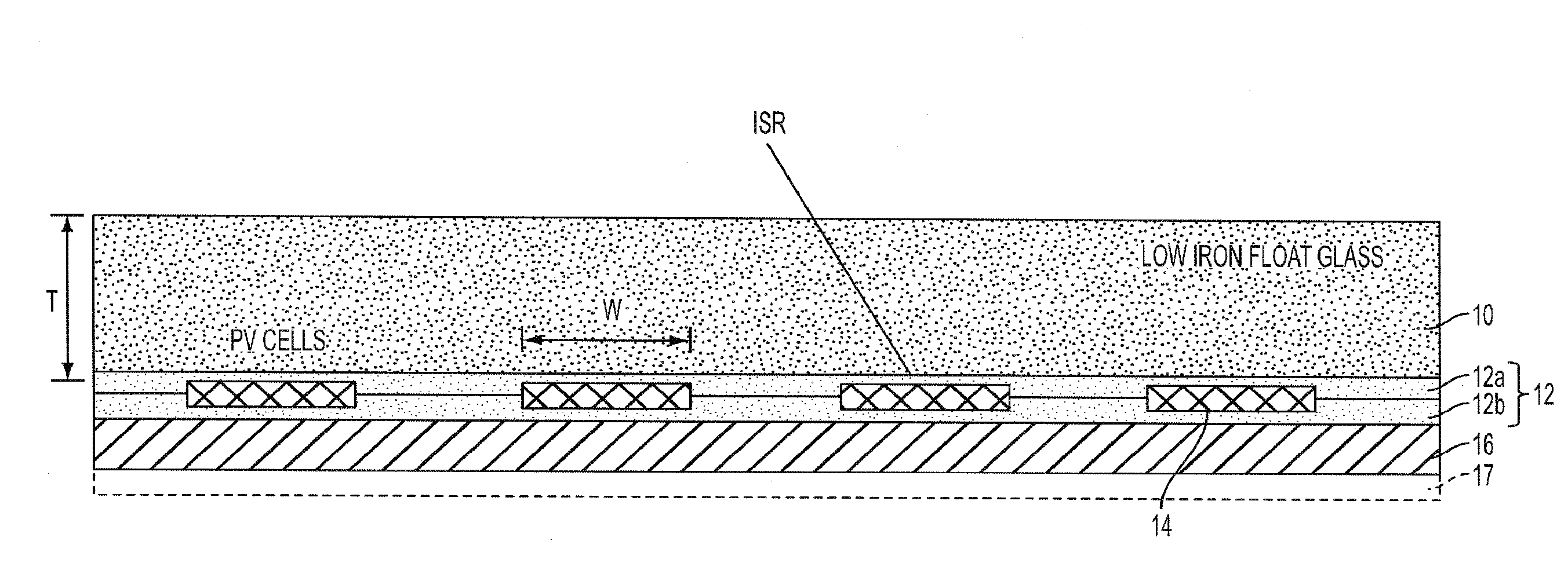
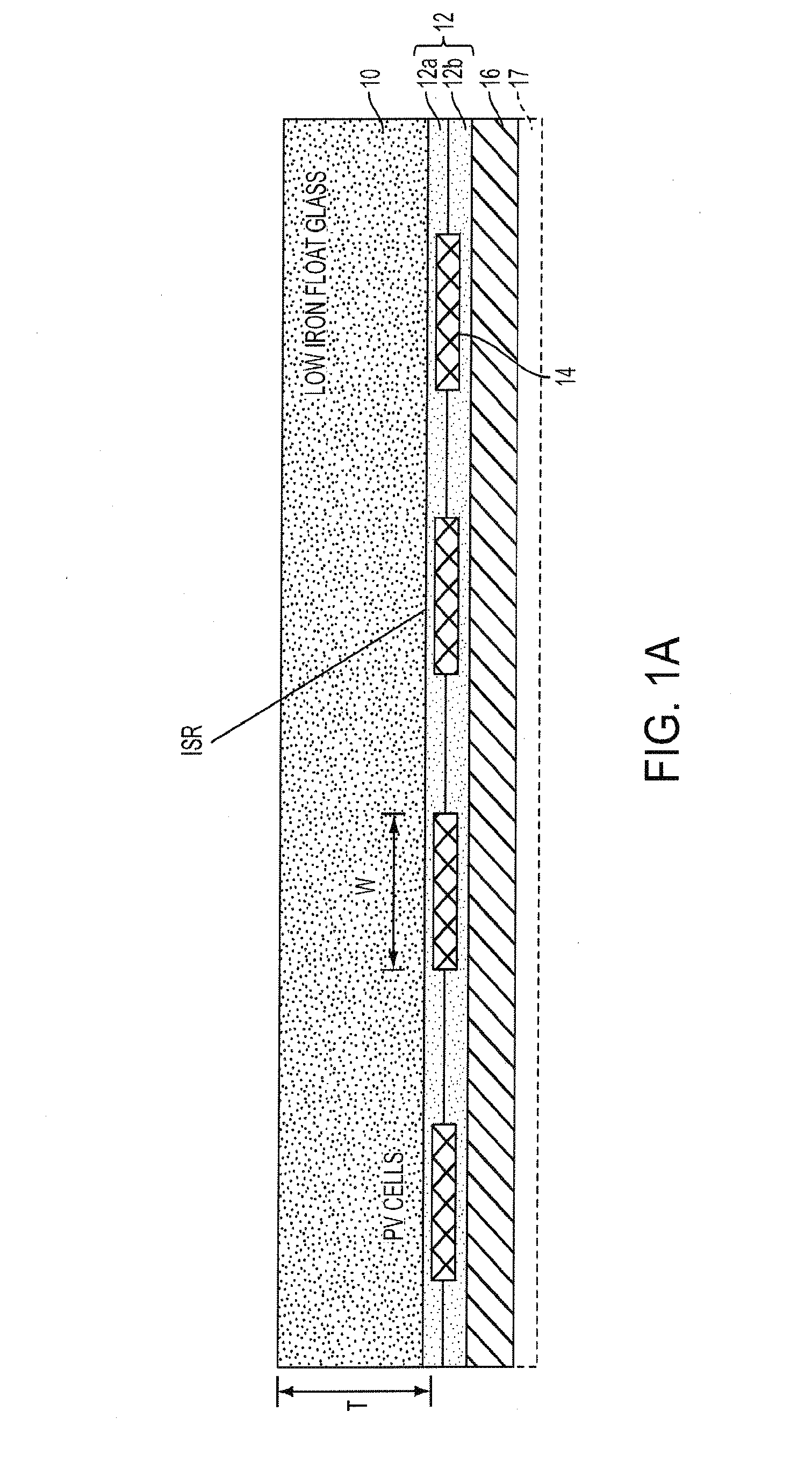
[0025]FIG. 1A shows a schematic cross-sectional view diagram of a luminescent solar concentrator apparatus in accordance with a

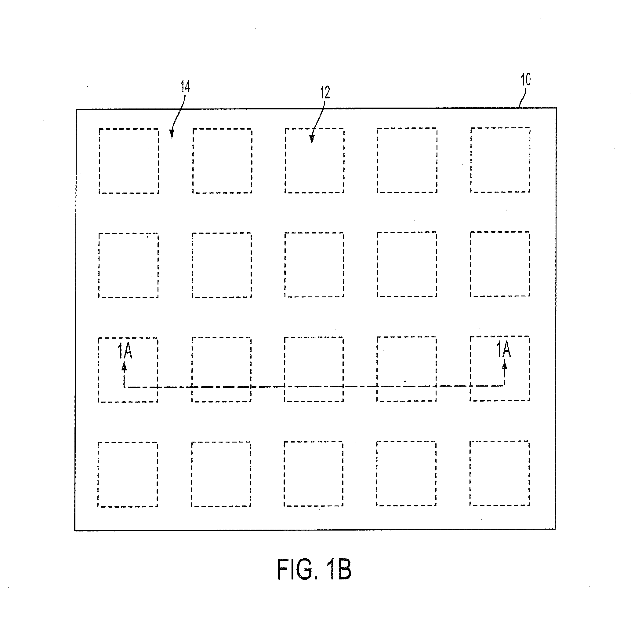
[0026]This particular luminescent solar concentrator apparatus in accordance with the first embodiment comprises in a first instance a transparent substrate 10. An encapsulant material layer 12 (which comprises a first encapsulant material sub-layer 12a and a second encapsulant material sub-layer 12b) is located and formed over and contacting one side of the transparent substrate 10. Incorporated within the encapsulant material layer 12 and interposed between and contacting the first encapsulant material sub-layer 12a and the second encapsulant material sub-layer 12b is a plurality of photovoltaic material layers 14 (i.e., each having a width W planar with the transparent substrate 10) that are intended as either individual photovoltaic material layers as photovoltaic cells, or a single interconnected photovoltaic material layer photovoltaic cell. FIG. 1 als...

second embodiment

[0046]FIG. 2 shows a schematic cross-sectional view diagram of a luminescent solar concentrator apparatus in accordance with a

[0047]Within the luminescent solar concentrator apparatus in accordance with the second embodiment as illustrated within the schematic cross-sectional diagram of FIG. 2, the layers and structures are generally similar with the layers and structures that are illustrated in the luminescent solar concentrator apparatus in accordance with the first embodiment as illustrated in FIG. 1A, but with the following exceptions. First, a top surface and interface of an encapsulant material layer 12′ (that in particular comprises a first encapsulant material sub-layer 12a′ and a second encapsulant material sub-layer 12b) with the bottom surface of the transparent substrate 10 is not entirely planar as illustrated within the schematic cross-sectional diagram of FIG. 1A with respect to the encapsulant material layer 12. In addition the second portion of the encapsulant mater...


PUM


Abstract

A luminescent solar concentrator apparatus includes an optically transparent substrate and a photovoltaic material layer at least partially embedded within an optically transparent encapsulant material layer that contacts the optically transparent substrate. A luminescent material layer also contacts the optically transparent encapsulant material layer. Generally, the luminescent solar concentrator apparatus provides that the luminescent material layer is not located within an incoming optical pathway through at least the optically transparent substrate to the photovoltaic material layer.

Description

CROSS-REFERENCE TO RELATED APPLICATION[0001]This application is related to, and derives priority from, U.S. Provisional Patent application serial number 61 / 409,589, filed 3 Nov. 2010, and titled Luminescent Solar Concentrator Apparatus, Method and Applications, the content of which is incorporated herein fully by reference.BACKGROUND[0002]1. Field of the Invention[0003]Embodiments relate generally to photovoltaic energy conversion. More particularly, embodiments relate to luminescent solar concentrator apparatuses and methods within the context of photovoltaic energy conversion.[0004]2. Description of the Related Art[0005]Luminescent solar concentrator apparatuses have been employed for several decades as a means to reduce costs of photovoltaic energy conversion systems. To that end, luminescent solar concentrator apparatuses provide an efficient means to collect incident solar radiation over large surface areas and to guide the incident solar radiation onto much smaller surface are...

Claims


Application Information

Patent Timeline
IPC IPC(8): H01L31/055H01L31/18
CPCH01L31/0392H01L31/048H01L31/18H01L31/055Y02E10/52H01L31/0481H01L31/042H01L31/0547H01L31/052
Inventor POWELL, DAVIDALERS, GLENNOLSON, JEREMY
Owner ABENGOA SOLAR
Why Eureka
Try Eureka