Reader antenna and RFID electronic shelf including the same

a technology of electronic shelf and reader antenna, which is applied in the direction of polarised antenna unit combination, instruments, electromagnetic radiation sensing, etc., can solve the problems of poor mountability of the reader antenna on the shelf, drastic degraded recognition rate, poor stability of the reader antenna, etc., to improve the recognition rate, easy storage in an electronic shelf, and stable recognition of items

Inactive Publication Date: 2013-08-22
ELECTRONICS & TELECOMM RES INST
View PDF2 Cites 31 Cited by
  • Summary
  • Abstract
  • Description
  • Claims
  • Application Information

AI Technical Summary

Benefits of technology

[0039]The reader antenna according to an exemplary embodiment of the present invention can be easily stored in an electronic shelf because it is realized in an ultrathin structure using a single-layered dielectric substrate.
[0040]The RFID electronic shelf according to an exemplary embodiment of the present invention can stably recognize items, even if a plurality of items are displayed in an arbitrary form on the electronic shelf, by arranging a reader antenna on the electronic shelf according to the mounting position of the antenna and the display form of items.
[0041]The RFID electronic shelf according to an exemplary embodiment of the present invention can offer an improved recognition rate because a fading zone can be eliminated from an electronic shelf by forming a time-varying near field on the electronic shelf by the use of both an antenna and a phase shifter block.

Problems solved by technology

The RFID technology of the HF band employing magnetic coupling is being studied in the RFID electronic shelf field, placing stress on excellent field characteristics for liquids and metals compared to the UHF band, but the recognition rate is drastically degraded due to interference between RFID tags, interference between tags and readers, and the like.
However, there is still a problem of recognition rate degradation due to a fading zone, caused by a change made to items to be displayed and a display method, and a polarization mismatch caused by the direction of tags to be displayed.
Particularly, a conventional fixed reader antenna is directly applied to an electronic shelf in most cases because little research has been conducted regarding a reader antenna for an RFID electronic shelf in the UHF band.
This leads to poor mountability of the reader antenna on the shelf.
Moreover, some reader antennas being studied for RFID electronic shelf applications in the UHF band cannot solve the problem of misrecognition caused by a polarization mismatch with tags, and a fading zone.
However, there are many difficulties in designing a reader antenna for an RFID electronic shelf having the above-mentioned characteristics by the conventional HF band antenna technology and the UHF band antenna technology.

Method used


Image

  • Reader antenna and RFID electronic shelf including the same
  • Reader antenna and RFID electronic shelf including the same
  • Reader antenna and RFID electronic shelf including the same

Examples


Embodiment Construction

[0050]The present invention will be described more fully hereinafter with reference to the accompanying drawings, in which exemplary embodiments of the invention are shown. As those skilled in the art would realize, the described embodiments may be modified in various different ways, all without departing from the spirit or scope of the principles for the present invention.

[0051]In order to clarify the present invention, elements extrinsic to the description are omitted from the details of this description, and like reference numerals refer to like elements throughout the specification.

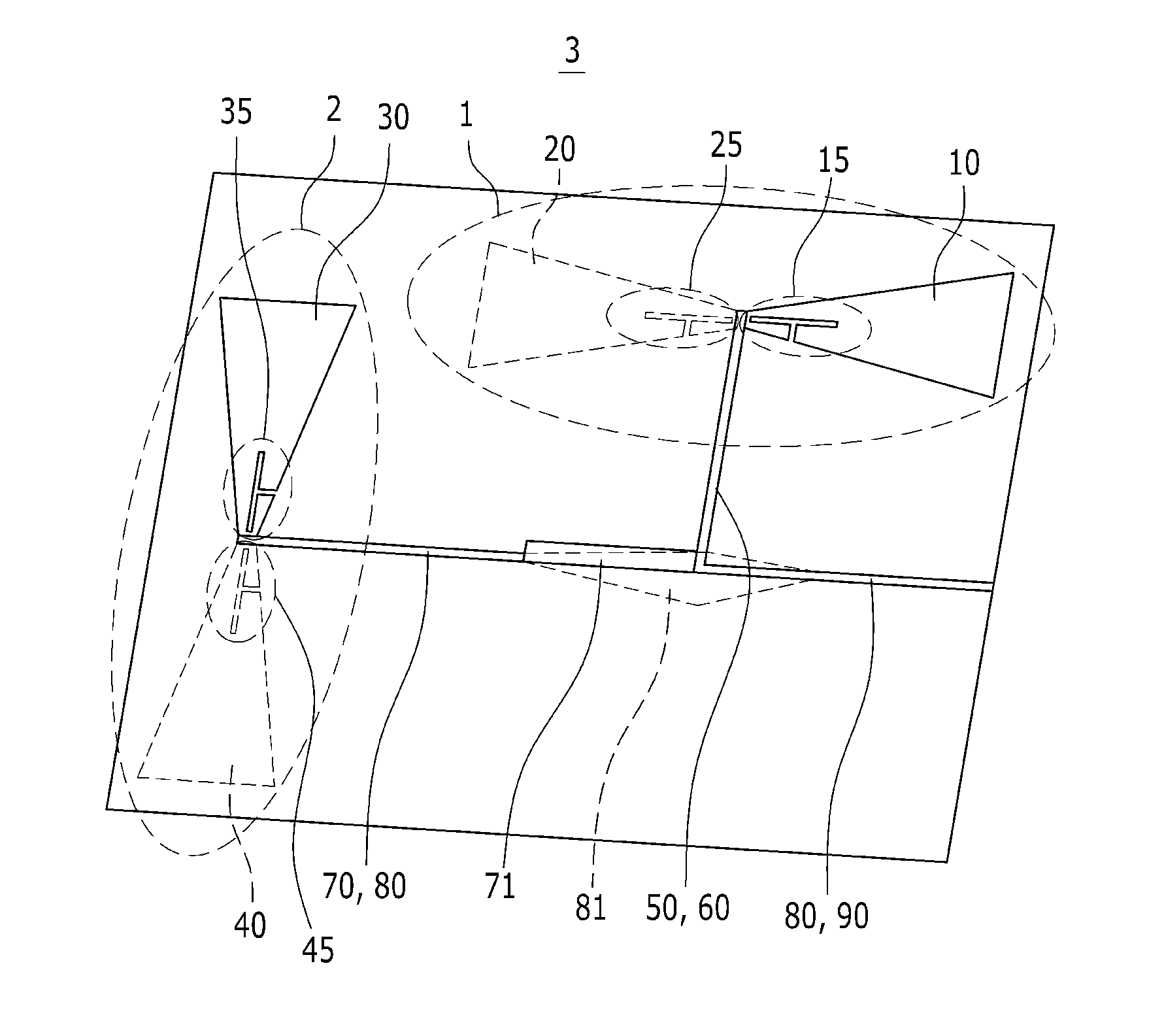
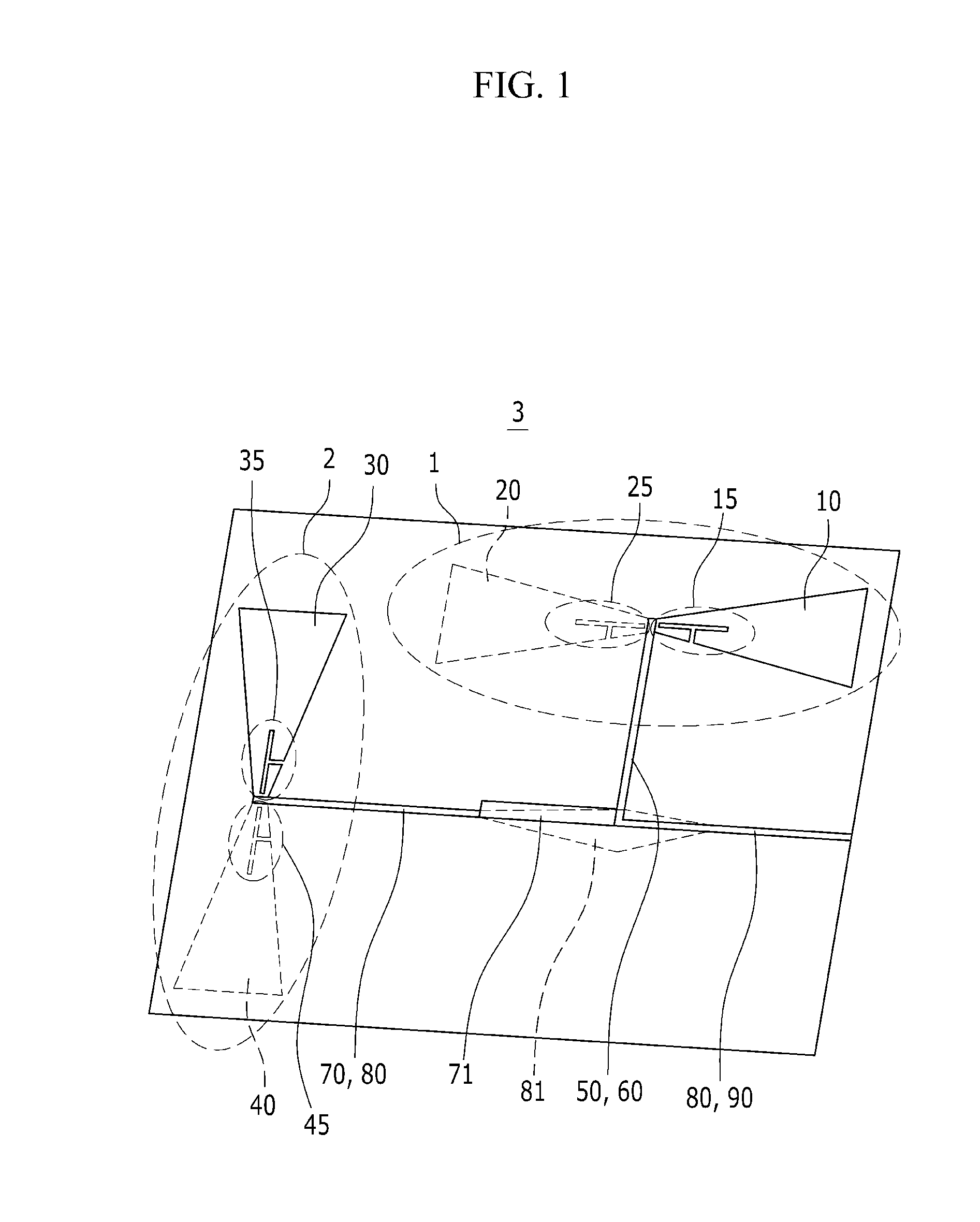
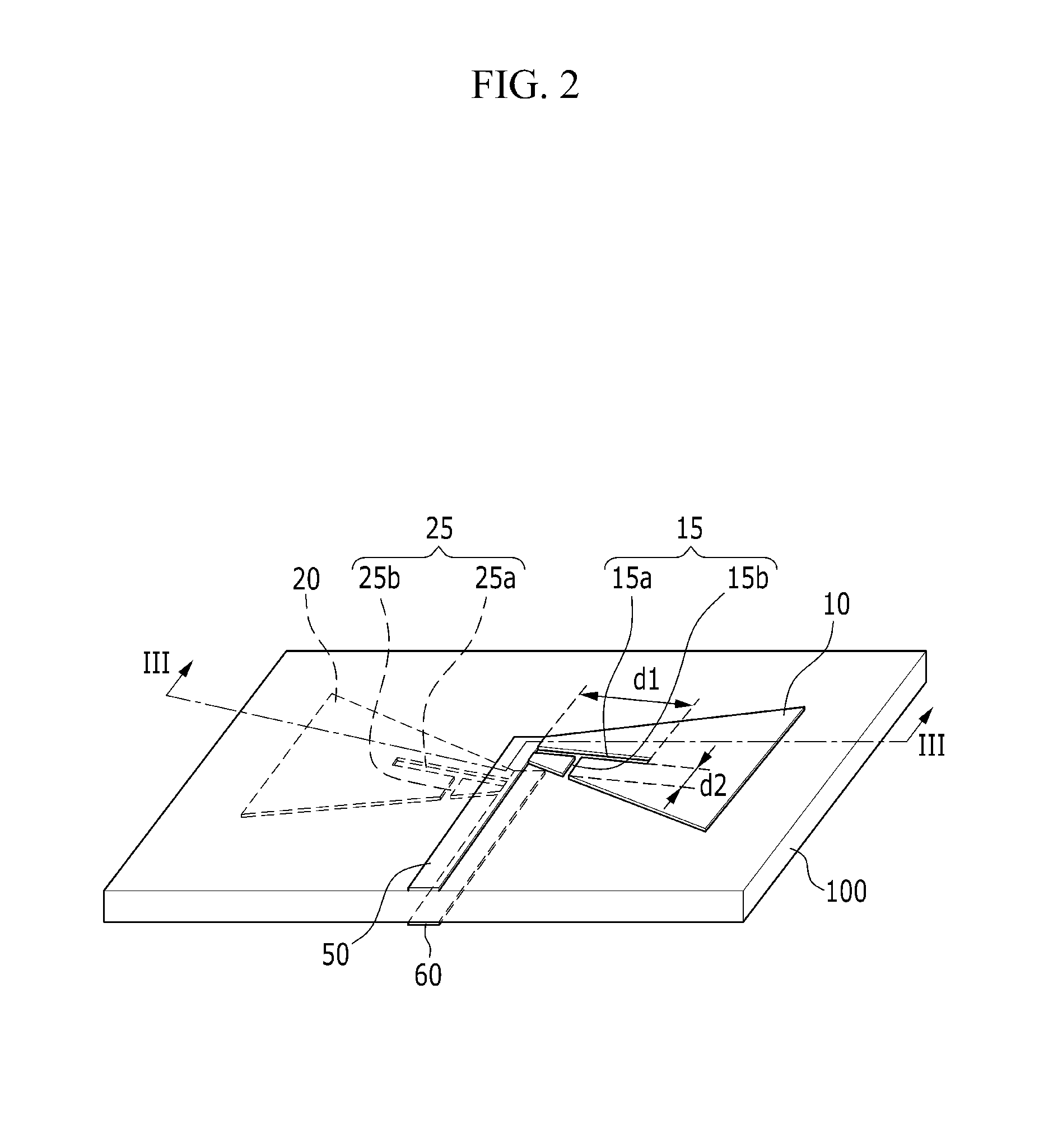
[0052]Now, a reader antenna according to a first exemplary embodiment of the present invention will be described in detail with reference to FIGS. 1 to 5.

[0053]FIG. 1 is a top plan view of a reader antenna according to a first exemplary embodiment of the present invention, FIG. 2 is a perspective view of a horizontal dipole antenna of the reader antenna according to the first exemplary embodiment of t...


PUM


Abstract

A reader antenna includes dipole antennas, the dipole antennas including: a horizontal dipole antenna having the characteristic of horizontal polarization; and a dipole antenna perpendicular to the horizontal dipole antenna and including a vertical dipole antenna having the characteristic of vertical polarization, wherein the horizontal dipole antenna and the vertical dipole antenna may both have the characteristic of circular polarization. The reader antenna can be easily stored in an electronic shelf because it is realized in an ultrathin structure using a single-layered dielectric substrate.

Description

CROSS-REFERENCE TO RELATED APPLICATION[0001]This application claims priority to and the benefit of Korean Patent Application No. 10-2012-0016593 filed in the Korean Intellectual Property Office on Feb. 17, 2012, the entire contents of which are incorporated herein by reference.BACKGROUND OF THE INVENTION[0002](a) Field of the Invention[0003]The present invention relates to a reader antenna and an RFID electronic shelf including the same, and more particularly, to a reader antenna capable of simultaneously recognizing many individual items (item level tagging), and an RFID electronic shelf including the same.[0004](b) Description of the Related Art[0005]The application field of radio frequency identification (RFID) in the ultra-high frequency (UHF) band has been extending from case or box unit recognition to individual item recognition as it has been recently used for an RFID electronic shelf.[0006]The material and shape of items to be mounted on an RFID electronic shelf, the shape o...

Claims


Application Information

Patent Timeline
Patent Type & Authority Applications(United States)
IPC IPC(8): G06K7/10H01Q9/04H01Q9/16
CPCG06K7/10346H01Q9/16H01Q9/0407H01Q21/28H01Q9/285H01Q21/24H01Q1/2216H01Q9/065H01Q9/44H01Q21/06
Inventor CHOI, WON KYUJUNG, JAE-YOUNGJEONG, SEUNG-HWANBAE, JI-HOONCHOI, GIL YOUNGCHAE, JONG-SUKPARK, CHAN-WONPYO, CHEOL SIG
Owner ELECTRONICS & TELECOMM RES INST
Why Eureka
Try Eureka