Imaging device and imaging apparatus
a technology of imaging device and imaging apparatus, which is applied in the direction of material analysis, instruments, radiation control devices, etc., can solve the problem of increasing and achieve the effect of reducing the amount of information to be output from the imaging devi
- Summary
- Abstract
- Description
- Claims
- Application Information
AI Technical Summary
Benefits of technology
Problems solved by technology
Method used
Image
Examples
first embodiment
1. First Embodiment
[0048]The first embodiment will be described below with reference to the attached drawings. A video camera will be taken as an example of the embodiment.
1-1. Overview
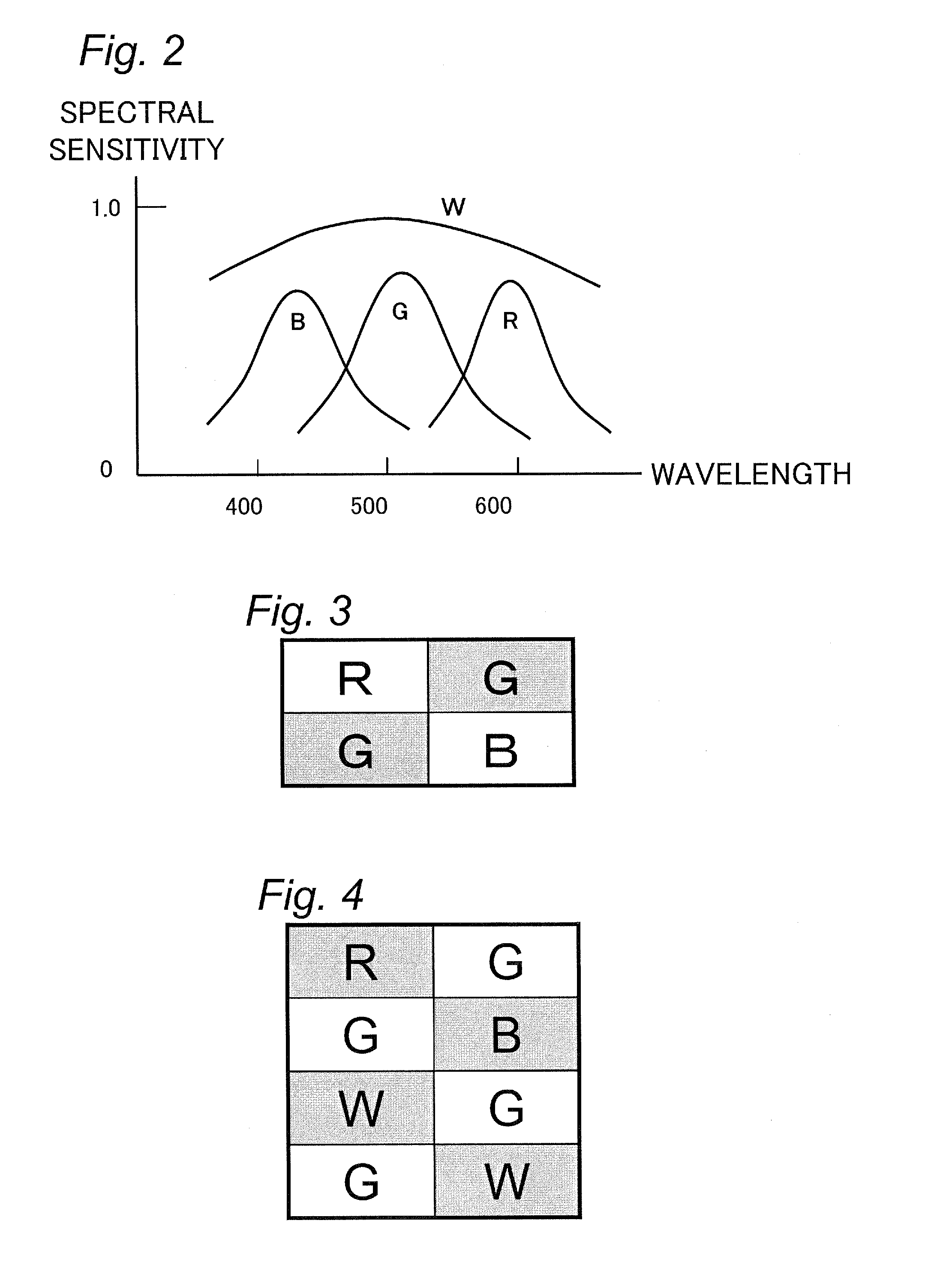
[0049]The video camera of the present embodiment is capable of taking a still image and a moving image by using the same imaging device (a CMOS image sensor in the present embodiment). Further, color filters of the CMOS image sensor installed in the video camera according to the present embodiment are arrayed to be able to output signals corresponding to the Bayer array after four kinds of pixels are mixed. That filter array enables the video camera to output image information more efficiently both in shooting a still image and in shooting a moving image by using the same imaging device.
[0050]The configuration and the operation of the video camera according to the present embodiment will be described below with reference to the drawings.
1-2. Configuration of Video Camera
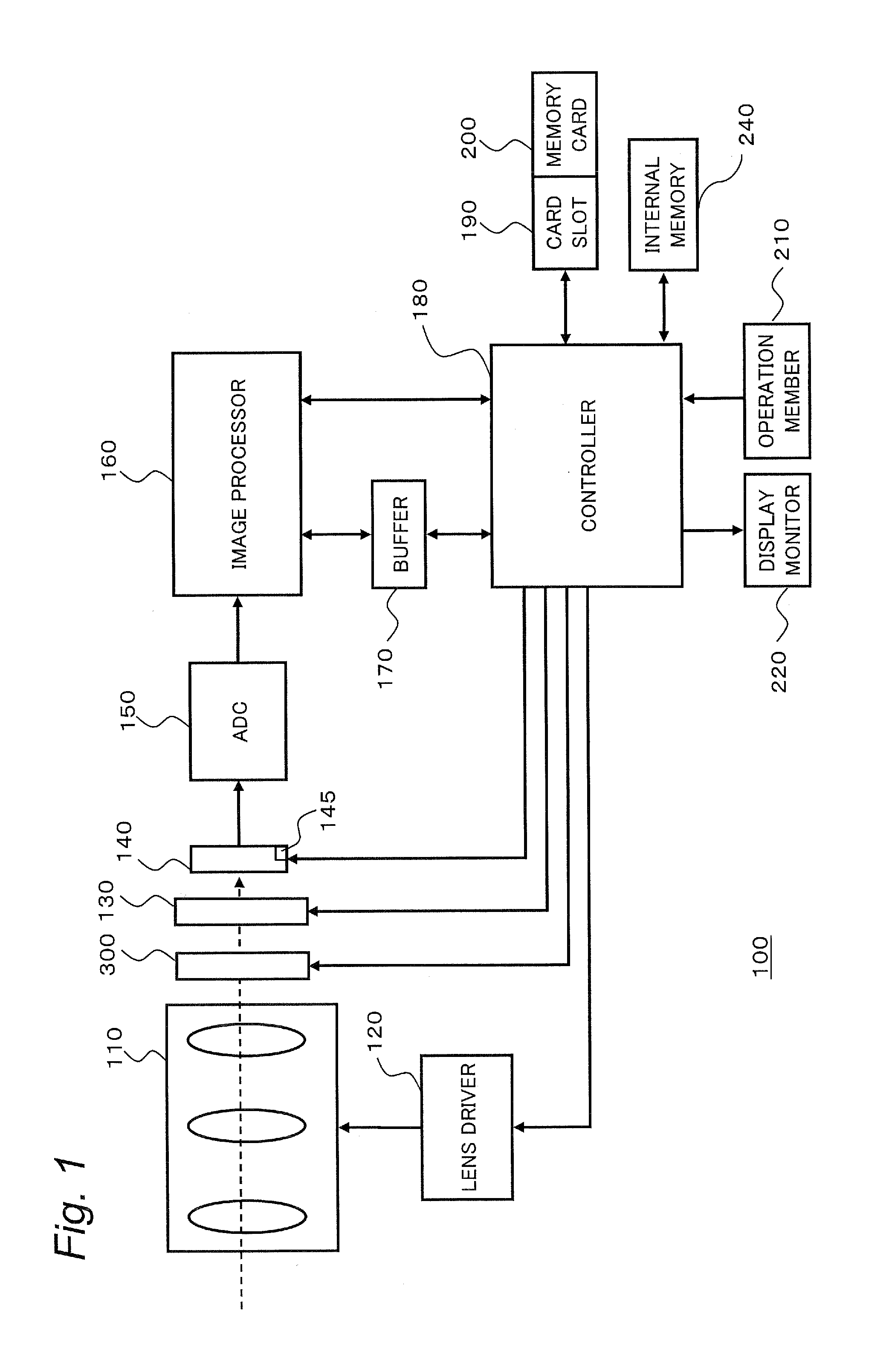
[0051]The electrical configurat...
second embodiment
2. Second Embodiment
[0116]The second embodiment will be described below.
[0117]The configuration and the operation of the video camera 100 according to the present embodiment are basically the same as those of the video camera 100 of the first embodiment. However, the method of adding pixels according to the present embodiment differs from that of the first embodiment.
[0118]FIG. 9 is a diagram for describing the pixel addition in the present embodiment. The filter array according to the present embodiment is the same as that of the first embodiment.
[0119]In the first embodiment (FIG. 7), four pixels are added up for each of the pixels Grs and Gbs. Unlike that, in the present embodiment, six pixels are added up for each of the pixels Grs and Gbs. As for the pixels of the other colors (R, B, and W), four pixels are added up as in the first embodiment.
[0120]Specifically, the adder 145 of the CMOS image sensor 140 performs the operation with the expression 8 below on the output signals f...
third embodiment
3. Third Embodiment
[0126]The third embodiment will be described below with reference to FIG. 11 to FIG. 14.
[0127]The basic array of the present embodiment differs from that of the first embodiment (FIG. 4). Accordingly, the positions of the pixels to be subject to the pixel addition differ from those of the first embodiment. The configuration and the operation of the video camera 100 except for the above described points are the same as those of the first embodiment.
[0128]FIG. 11 is a diagram illustrating a basic array of pixels in the present embodiment.
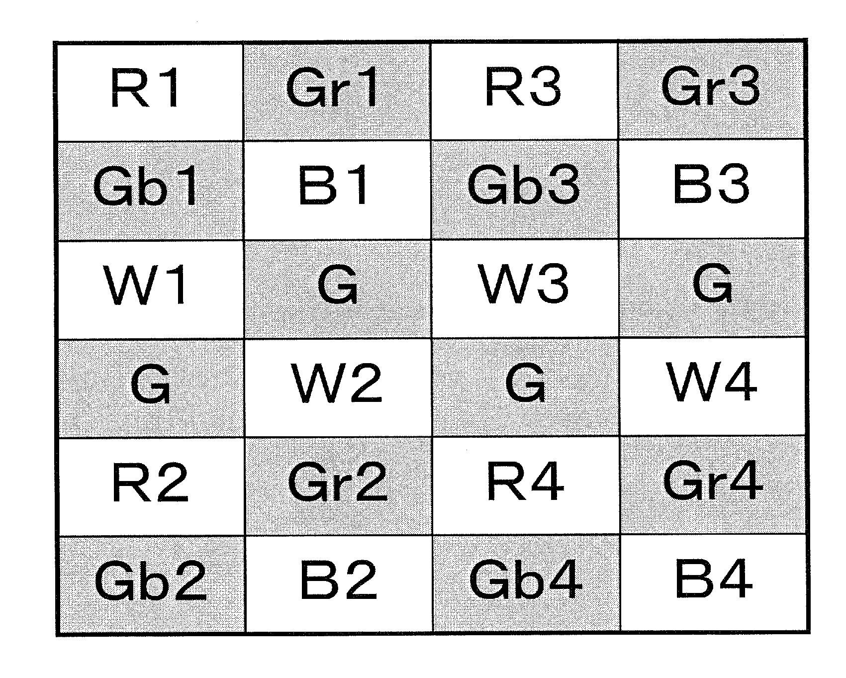
[0129]As illustrated in FIG. 11, the basic array of color filters in the present embodiment is the array with six rows and two columns. Also in the basic array according to the present embodiment, four kinds of color filters (R, G, B, and W) are arrayed and the G filters are checkered as in the basic array of the first embodiment (FIG. 4).
[0130]FIG. 12 is a diagram illustrating the pixel array including the basic array according to ...
PUM
 Abstract
Description
Claims
Application Information
 - R&D
- Intellectual Property
- Life Sciences
- Materials
- Tech Scout
- Unparalleled Data Quality
- Higher Quality Content
- 60% Fewer Hallucinations
Browse by: Latest US Patents, China's latest patents, Technical Efficacy Thesaurus, Application Domain, Technology Topic, Popular Technical Reports.
© 2025 PatSnap. All rights reserved.Legal|Privacy policy|Modern Slavery Act Transparency Statement|Sitemap|About US| Contact US: help@patsnap.com


