Controller for an Electronic Line-Scan Camera

a technology of electronic linescan and controller, which is applied in the direction of instruments, television systems, material analysis, etc., can solve the problems of difficult arbitrary use of such electronic cameras, distortion could be generated, etc., and achieve the effects of increasing image capture rate, facilitating image information, and facilitating output faster

Active Publication Date: 2008-05-01
BASLER AG
View PDF2 Cites 1 Cited by
  • Summary
  • Abstract
  • Description
  • Claims
  • Application Information

AI Technical Summary

Benefits of technology

[0010]A special advantage of the invention is that a camera with multiple lines controlled in this way operates significantly faster than a single-line line-scan camera. For a single-line line-scan camera, the image information is read out and then output after each exposure. According to the invention, it is provided that all of the exposed lines are read out after an exposure. The image information of the individual lines is stored or held according to the sensor construction until it is retrieved and output line by line. This can be performed in succession either based on subsequent trigger signals or automatically. The read-out process is frequently the limiting time factor in single-line line-scan cameras. Because the lines in multiple-line line-scan cameras can be read out in parallel time-wise, the image information of several successive lines is available after only one read-out process. Accordingly, the output can be performed more quickly. Here it is possible to start the exposure while the read-out or output process is still running.
[0011]It is useful when a new exposure of the lines of the sensor is performed after a number of trigger signals corresponding to the number of lines exposed after the preceding first trigger signal. It is also useful when the image information of an exposed line for output is stored or held based on the trigger signal allocated to the line. Then the multiple-line line-scan camera behaves on the user side like a single-line line-scan camera.
[0012]Through the control according to the invention, the image information of one line is output on the basis of each external trigger signal. The special feature consists in that, for an n-line camera, only every nth external trigger signal leads to an exposure of the light-sensitive lines. The external trigger signals lying in-between are used, in particular, for retrieving the image information of the lines that have been previously already exposed and allocated to the relevant trigger signals. With the control according to the invention, multiple-line line-scan cameras can be controlled so that they behave like single-line line-scan cameras on the user side. The number of exposed lines, whose image information has been retrieved, can correspond to or be less than the number of lines of the sensor. In addition, it is possible to increase the image capture rate, because the image information becomes available more quickly.
[0013]With this control, it is correspondingly possible to use a multiple-line line-scan camera instead of a single-line line-scan camera. Because the camera is controlled in the same way as in a single-line line-scan camera, no other type of trigger signal or especially adapted trigger signal must be generated. The external trigger signals, which are generated on the object side or on the user side and which are not set as the first trigger signals, can be used or rejected for line-by-line output of the image information. After all of the lines have been read out, the next external trigger signal is set as a first trigger signal, which triggers an exposure of all of the lines of the camera provided for exposure. The subsequent external trigger signals do not cause a new exposure of the camera or its sensor but instead only the line-by-line output of the image information of the already exposed lines. Consequently, the output of the image information also matches that of a single-line line-scan camera. Therefore, a multiple-line line-scan camera can be easily integrated into existing systems, for example, into production lines.

Problems solved by technology

Otherwise distortion could be generated.
However, because the trigger signals are generated external to the camera on the object side, an arbitrary use of such electronic cameras is not always easily possible.

Method used


Image

  • Controller for an Electronic Line-Scan Camera
  • Controller for an Electronic Line-Scan Camera

Examples


Embodiment Construction

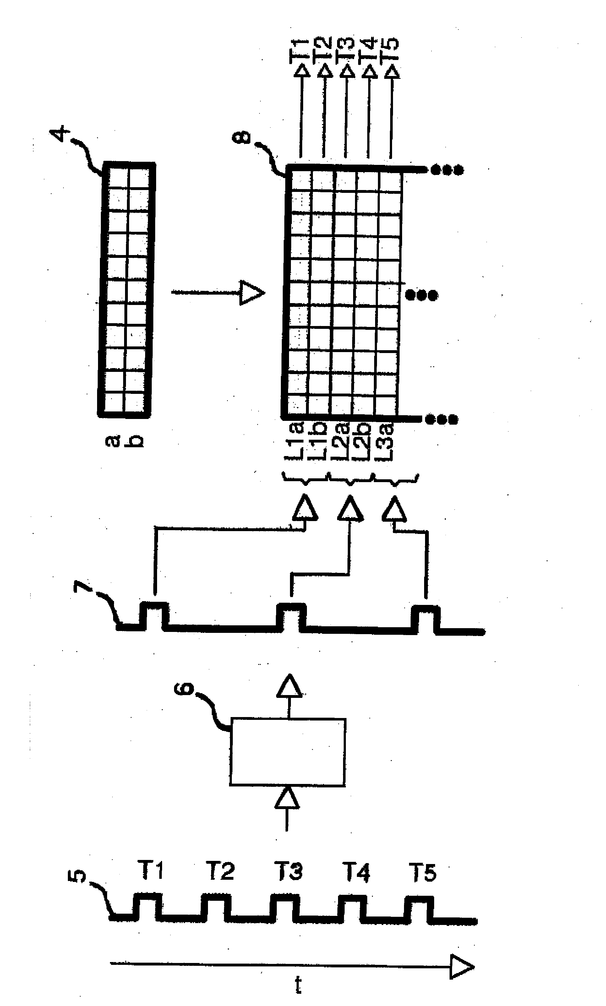
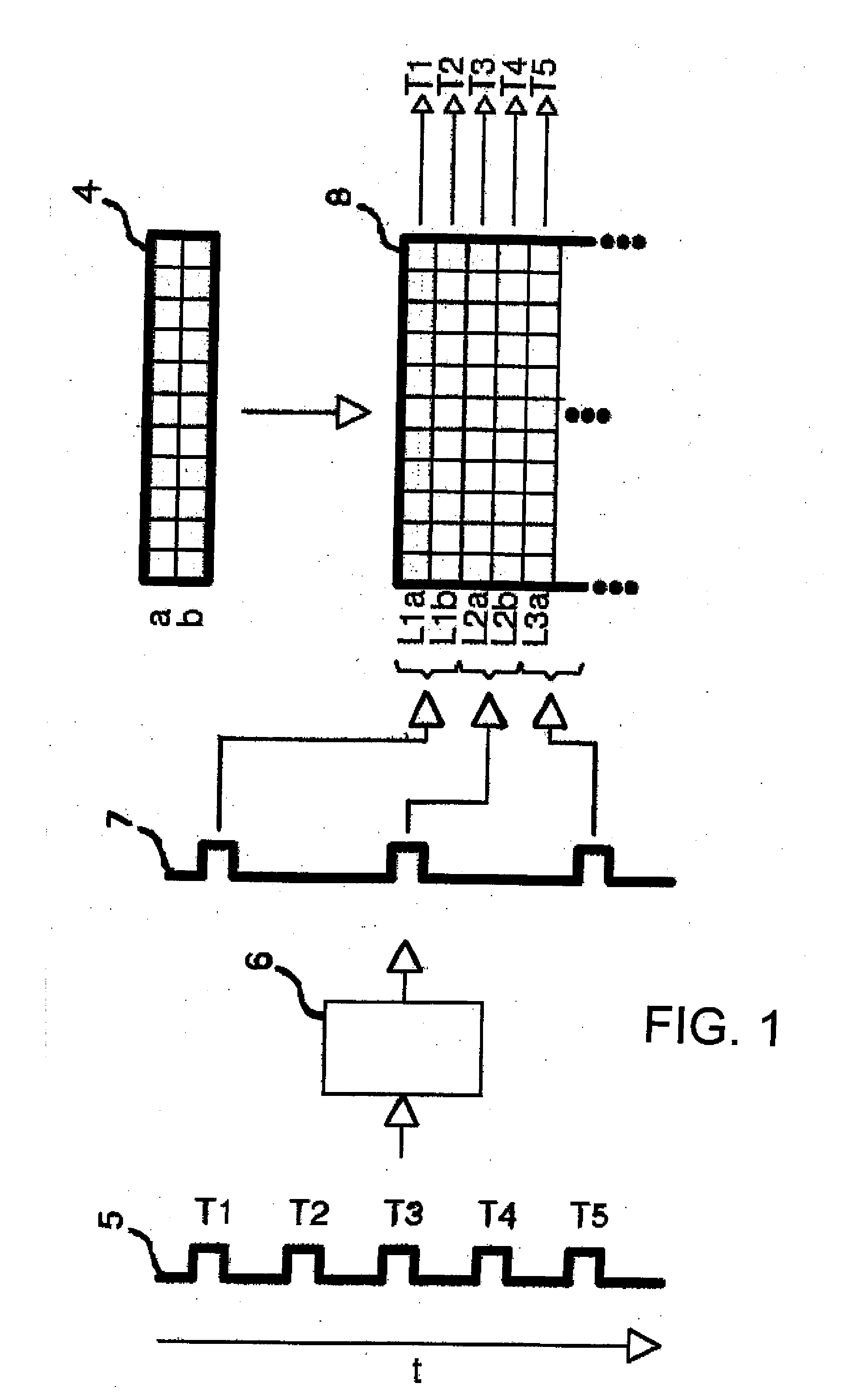
[0015]In the drawing, the signal flow for controlling an electronic camera is shown schematically. In the embodiment shown, for example, due to the motion of an object, external trigger signals T1, T2 . . . T5 following each other spatially are generated. These trigger signals can be, for example, feed-controlled, if the object to be scanned is moved and is located, for example, on an assembly line. An image line should be recorded at each of these external trigger signals 5. For uniformly moving objects, time-controlled trigger signals can also be used, which feature a time interval relative to each other. Usually, the trigger signals are generated continuously, so that a linear region of the object to be scanned is allocated to each trigger signal, with this region being adjacent to a directly adjacent linear region allocated to the previous trigger signal. Thus, the assembled image lines form the overall image of the object.

[0016]The image sensor 4 of the electronic camera is for...


PUM


Abstract

A method for controlling an electronic line-scan camera having at least two lines with light-sensitive pixels by means of external trigger signals. A predetermined number of lines of the sensor are exposed due to a first external trigger signal and the image information of the first exposed line and that of the subsequent line or lines are each output successively.

Description

BACKGROUND OF THE INVENTION[0001]The invention relates to a method for controlling an electronic line-scan camera, which has at least two lines with light-sensitive pixels, by means of external trigger signals.[0002]It is known to scan continuous production processes or moving objects optically by means of line-scan cameras. Here, the camera and the object move relative to each other, with the motion taking place perpendicular to the sensor lines. Usually, the process takes place such that a trigger signal is generated as a function of the motion of the object, with the electronic camera being triggered by this trigger signal at certain sections of the object or certain times. A linear image is generated. Through successive linear scanning and assembly of several successive image lines in series, the entire object can be scanned and imaged.[0003]For line-scan cameras with only one line, a trigger signal triggers exposure of the entire line, and then the image information is output. ...

Claims


Application Information

Patent Timeline
Patent Type & Authority Applications(United States)
IPC IPC(8): H01L27/00
CPCG01N2021/8887H04N1/193H04N1/1934H04N5/3692H04N1/195H04N5/232H04N5/353H04N1/1938H04N25/53H04N25/701
Inventor KUNZE, JOERG
Owner BASLER AG
Why Eureka
Try Eureka