
Method for determining a sensor value and sensor system

a sensor value and sensor technology, applied in the direction of resistance/reactance/impedence, instruments, force measurement, etc., can solve the problem that the sensor value of the strain gauge is sensitive to environmental effects, and achieve the effect of increasing the accuracy of determining the sensor valu

Inactive Publication Date: 2013-08-22
SONY MOBILE COMM INC
View PDF4 Cites 51 Cited by
  • Summary
  • Abstract
  • Description
  • Claims
  • Application Information

AI Technical Summary

Benefits of technology

This patent describes a method for accurately measuring strain and temperature using a strain gauge sensor. The sensor has two characteristic dependencies that indicate its resistance to temperature and strain at different electrical voltages. These dependencies can be mathematical formulas or look-up tables. The sensor value is determined based on a combination of these dependencies, the first and second electrical resistances, and the temperature. The method ensures high accuracy, even when the changes in resistance are small. The electrical supply voltage can range from 0.1 to 3.0 V, and may exceed 3.0 V for increased accuracy. This allows the sensor to be easily integrated into mobile devices.

Problems solved by technology

However, strain gauge sensors are very sensitive for environmental effects such as temperature changes.

Method used


Image

  • Method for determining a sensor value and sensor system
  • Method for determining a sensor value and sensor system
  • Method for determining a sensor value and sensor system

Examples


Embodiment Construction

[0021]In the following, exemplary embodiments of the invention will be described in more detail. It has to be understood that the following description is given only for the purpose of illustrating the principles of the invention and is not to be taken in a limiting sense. Rather, the scope of the invention is defined only by the appended claims and is not intended to be limited by the exemplary embodiments hereinafter.

[0022]It is to be understood that the features of the various exemplary embodiments described herein may be combined with each other unless specifically noted otherwise. Same reference signs in the various drawings and the following description refer to similar or identical components.

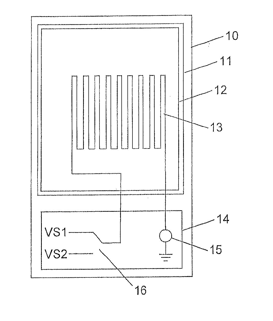
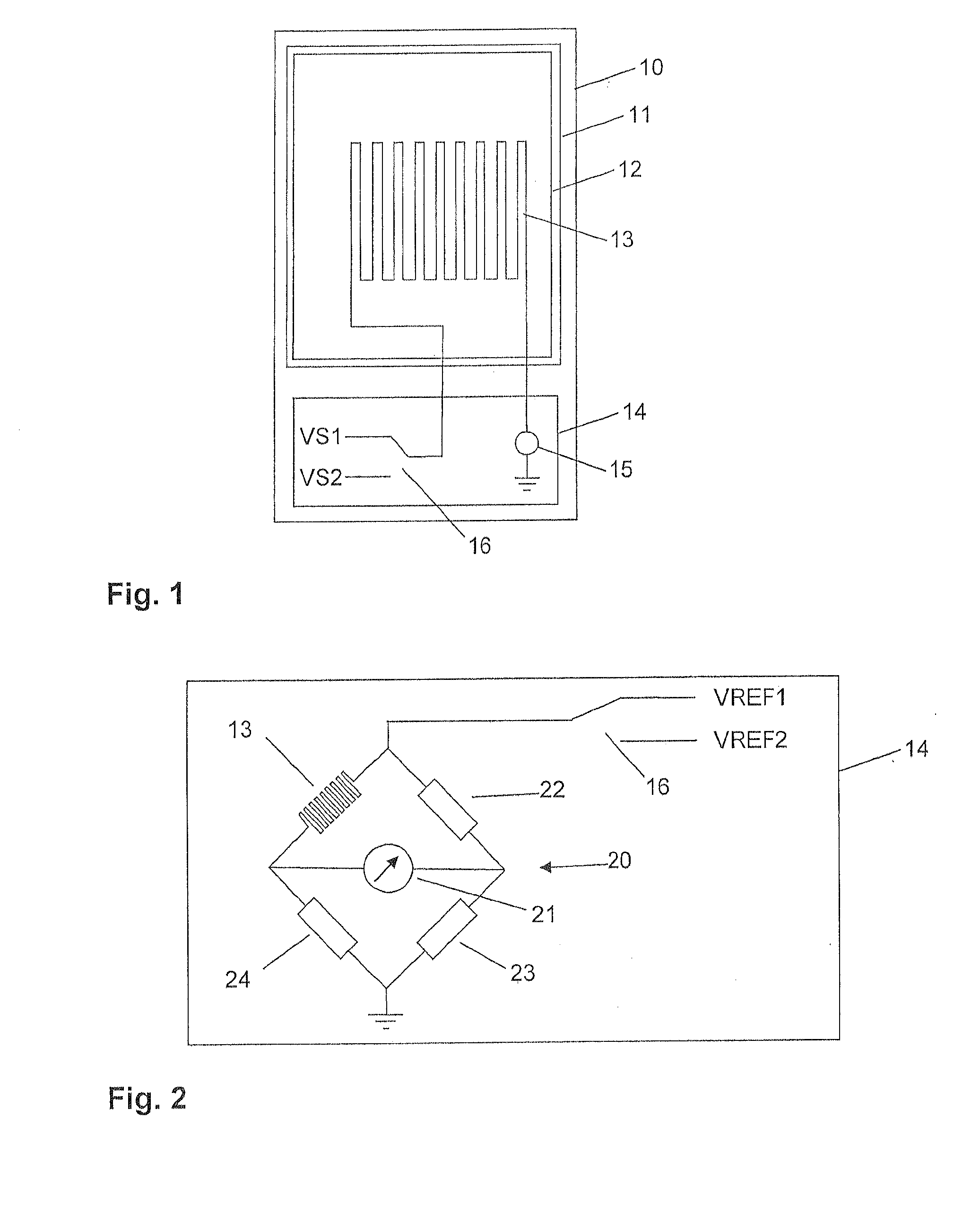
[0023]FIG. 1 shows a mobile device 10, for example a mobile phone. The mobile device 10 comprises among other parts (not shown) a display 11 and a touch panel 12 which is arranged on top of the display 11. The touch panel 12 may comprise a glass window and an array or grid of electrodes ...


PUM


Abstract

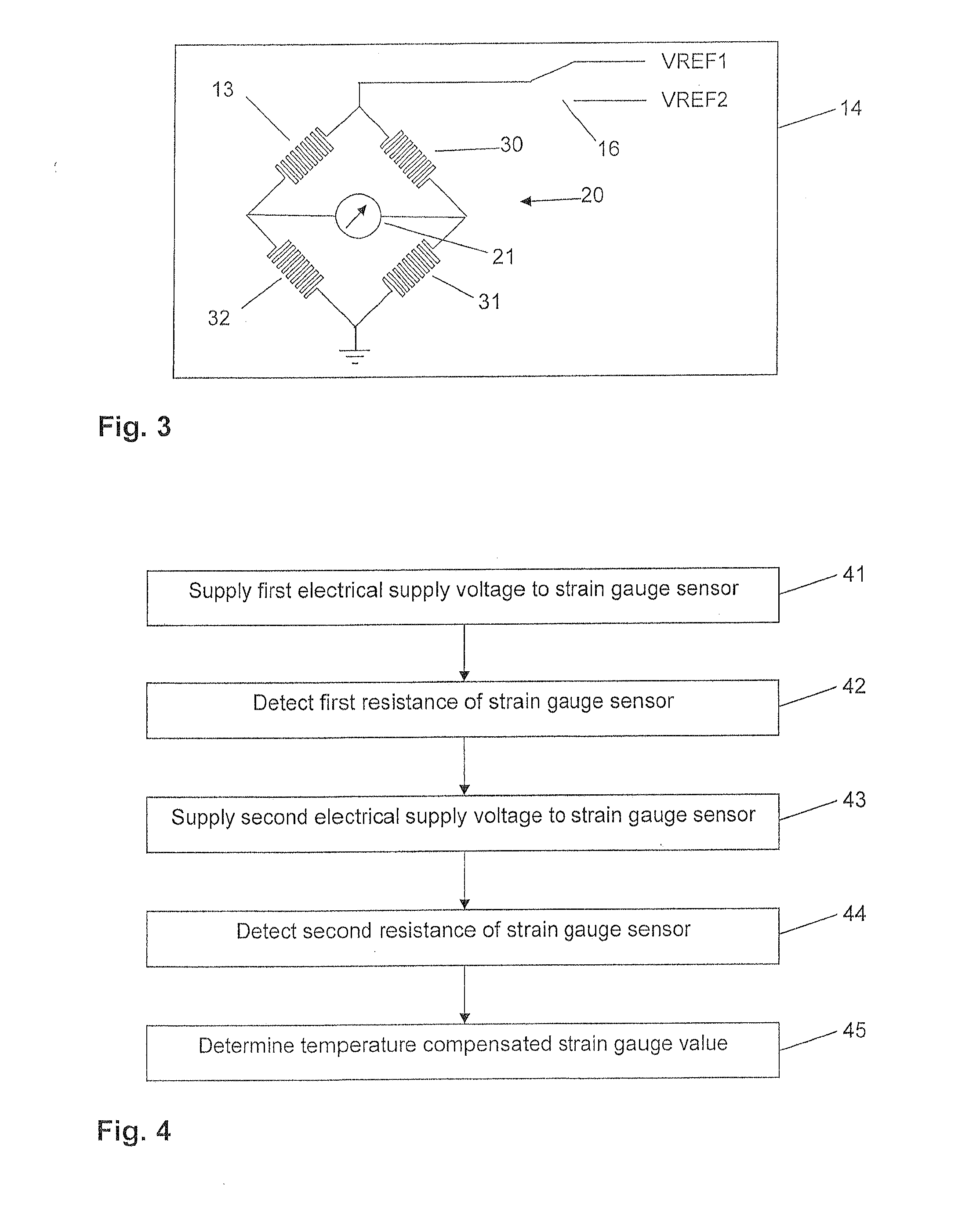
For determining a sensor value of a sensor (13), a first electrical supply voltage (VS1) is supplied to the sensor (13) and a first electrical resistance of the sensor (13) is detected. Then, a second electrical supply voltage (VS2) is supplied to the sensor and a second electrical resistance of the sensor (13) is detected. The second electrical supply voltage (VS2) is different from the first electrical supply voltage (VS1). The sensor value is automatically determined depending on the first electrical supply voltage (VS1), the second electrical supply voltage (VS2), the first electrical resistance, and the second electrical resistance.

Description

FIELD OF THE INVENTION[0001]The present invention relates to a method for determining a sensor value of a sensor, especially to a method for determining a temperature compensated strain gauge value of a strain gauge sensor. The present application relates furthermore to a sensor system, a touch sensitive user interface comprising the sensor system, and a mobile device comprising the touch sensitive user interface.BACKGROUND OF THE INVENTION[0002]Touch panels are known in the art for controlling devices via a user interface. The touch panel may be arranged on top of a display forming a so-called touch screen. A touch screen provides a very intuitive way of operating the device. Information may be displayed on the display and in response to the information displayed on the display, the user may touch the display for initiating actions or operations. The touch panel may work by detecting a change of capacity when the user approaches or touches the surface of the touch panel. Such a so-...

Claims


Application Information

Patent Timeline
IPC IPC(8): G01R27/14G06F3/041
CPCG01R27/14G06F3/0414G01L1/2281G01R31/2829G01D3/036
Inventor JOHANSSON, ALLANKNUTSSON, LARSBERG, PETERROSQVIST, BJORN
Owner SONY MOBILE COMM INC
Learn More