Cube-corner retroreflective sheeting

a retroreflective sheeting and cube-corner technology, applied in the direction of instruments, roads, constructions, etc., can solve the problems of low brightness around the boundary, inferior design, and the inability to make less boundaries, and achieve excellent design and excellent rotation angle characteristics

Active Publication Date: 2013-08-22
NIPPON CARBIDE KOGYO KK
View PDF3 Cites 6 Cited by
  • Summary
  • Abstract
  • Description
  • Claims
  • Application Information

AI Technical Summary

Benefits of technology

[0049]As described above, according to the present invention, cube-corner retroreflective sheeting that is excellent in rotation angle characteristics and excellent in design is provided.

Problems solved by technology

Appropriate retroreflected light cannot therefore be obtained around the boundaries between the regions, which results in low brightness around the boundaries.
As a result, the hexagonal cube-corner retroreflective sheeting taught in Patent Documents 5 to 7 has a problem that the boundaries between the regions become conspicuous, which is inferior in design although the rotation angle is improved.
It is found, however, that elements that do not produce retroreflection are formed at boundaries between regions in which only hexagonal cube-corner retroreflective elements that are oriented in different directions from each other and the boundaries cannot be made less conspicuous.

Method used


Image

  • Cube-corner retroreflective sheeting
  • Cube-corner retroreflective sheeting
  • Cube-corner retroreflective sheeting

Examples


first embodiment

[0068](First Embodiment)

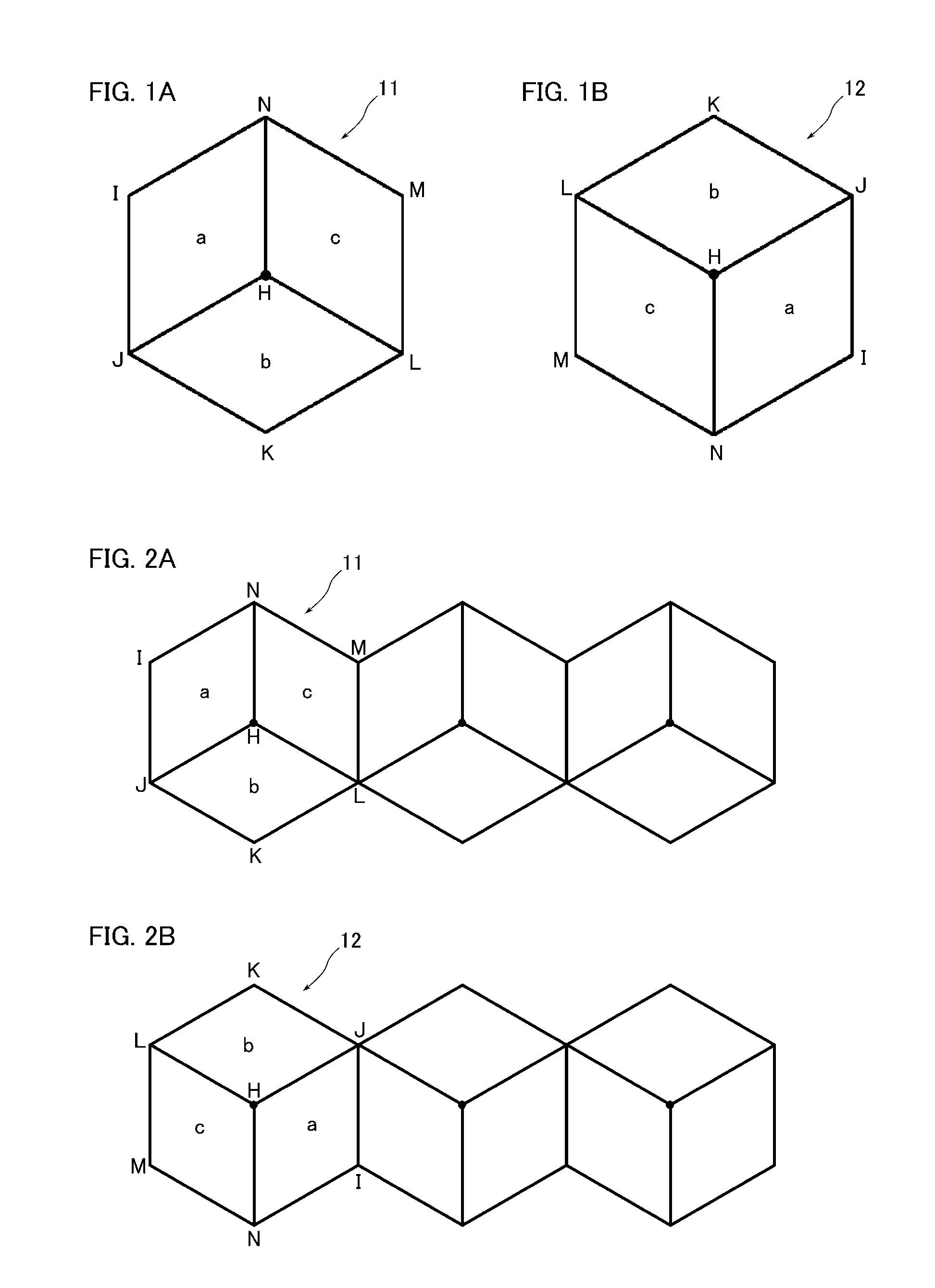
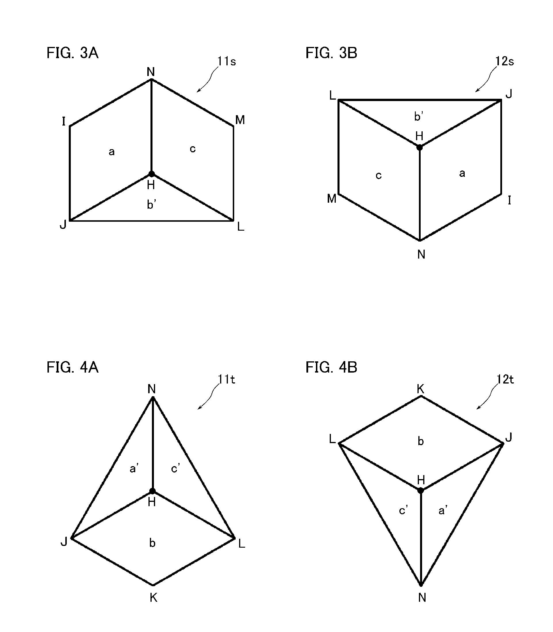
[0069]FIG. 1 shows enlarged views of hexagonal cube-corner retroreflective elements in cube-corner retroreflective sheeting according to a first embodiment of the present invention. As shown in (A) and (B) of FIG. 1, the cube-corner retroreflective elements in the present embodiment are hexagonal cube-corner retroreflective elements.

[0070]As shown in FIG. 1(A), a hexagonal cube-corner retroreflective element 11 has three quadrangular reflective lateral surfaces a, b and c that are congruent. The reflective lateral surface a is a square having apexes H, N, I and J, the reflective lateral surface b is a square having apexes H, J, K and L, and the reflective lateral surface c is a square having apexes H, L, M and N. The reflective lateral surfaces a, b and c therefore has one apex H in common. That is, the apex H is an apex of a cube-corner retroreflective element that three reflective lateral surfaces have in common. In addition, the adjacent reflective lateral...

second embodiment

[0088](Second Embodiment)

[0089]Next, a second embodiment of the present invention will be described in detail with reference to FIGS. 7 to 9. Here, components that are identical or similar to those in the first embodiment are designated by the same reference numerals and redundant description will not be repeated unless the description is particularly stated.

[0090]FIG. 7 shows views in which hexagonal cube-corner retroreflective elements of cube-corner retroreflective sheeting according to the second embodiment of the present invention are arranged, and corresponds to FIG. 2 in the first embodiment. FIG. 8 shows plan views of regions in the cube-corner retroreflective sheeting according to the present embodiment in which the cube-corner retroreflective elements are arranged in a closest-packed state, and FIG. 9 is a plan view showing the cube-corner retroreflective sheeting according to the present invention in which the regions of the cube-corner retroreflective sheeting shown in F...

third embodiment

[0096](Third Embodiment)

[0097]Next, a third embodiment of the present embodiment will be described in detail with reference to FIGS. 10 and 11. Here, components that are identical or similar to those in the first embodiment are designated by the same reference numerals and redundant description will not be repeated unless the description is particularly stated.

[0098]FIG. 10 is a plan view showing cube-corner retroreflective sheeting according to the third embodiment of the present invention, and FIG. 11 is a perspective view of the cube-corner retroreflective sheeting shown in FIG. 10.

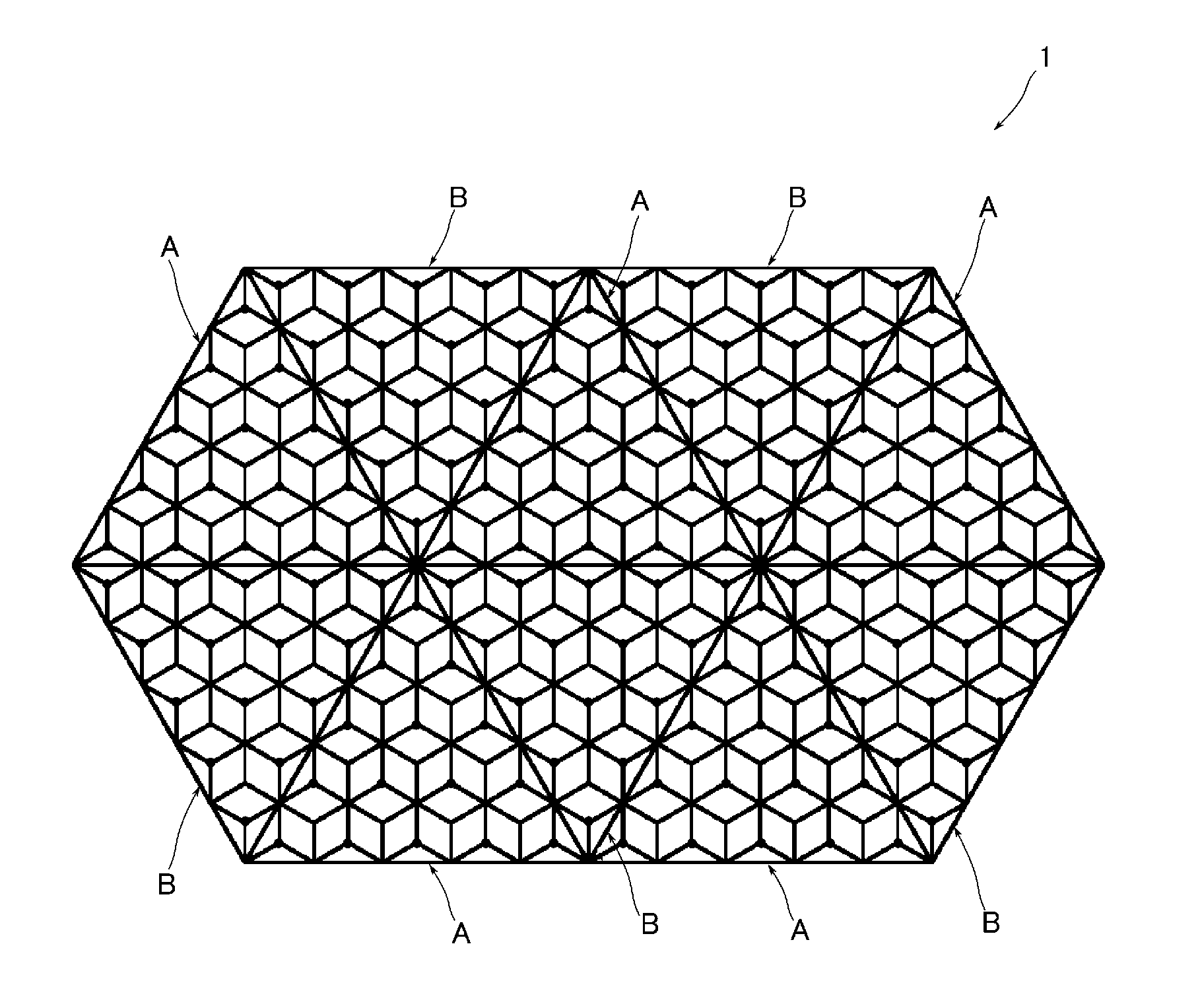
[0099]As shown in FIGS. 10 and 11, in cube-corner retroreflective sheeting 3, two regions A and B having rotation angle characteristics different from each other by 180 degrees are formed in belt-like shapes and the regions A and B are arranged alternately. A first outer edge of the region A is straight and a second outer edge of the region B is straight and a first outer edge thereof is zigzag. Accord...


PUM


Abstract

In cube-corner retroreflective sheeting 3, cube-corner retroreflective elements in at least two mutually adjacent regions A and B rotate with each other around an axis perpendicular to the sheeting, in which cube-corner retroreflective elements 11 and 12 not in contact with boundaries between the regions A and B are cube-corner retroreflective elements having a hexagonal shape, and cube-corner retroreflective elements 11s, 12s, 11t and 12t in contact with the boundaries between the regions A and B are cube-corner retroreflective elements having a shape obtained by cutting parts of one or two reflective lateral surfaces of the cube-corner retroreflective element having a hexagonal shape where the partly cut reflective lateral surfaces are in contact with the boundaries.

Description

TECHNICAL FIELD[0001]The present invention relates to cube-corner retroreflective sheeting, and particularly relates to cube-corner retroreflective sheeting that is excellent in rotation angle characteristics and excellent in design.BACKGROUND ART[0002]Retroreflective sheeting that reflects light in substantially the same direction as the incident direction has been used for signs such as road traffic signs and construction signs, vehicle registration plates, safety materials such as helmets and life preservers, markings such as those on signboards, and others. Hexagonal cube-corner retroreflective sheeting that is excellent in light reflective efficiency is known as one example of the retroreflective sheeting.[0003]In producing the hexagonal cube-corner retroreflective sheeting, respective hexagonal cube-corner retroreflective elements are formed by die molding. Specifically, hexagonal cube-corner retroreflective sheeting having a large area is formed by using a die assembly includ...

Claims


Application Information

Patent Timeline
Patent Type & Authority Applications(United States)
IPC IPC(8): G02B5/122E01F9/619
CPCG02B5/124G02B5/136G02B5/122
Inventor MIMURA, IKUO
Owner NIPPON CARBIDE KOGYO KK
Why Eureka
Try Eureka