Elastic supporting structure and optical image stabilizer having the elastic supporting structure

an optical image stabilizer and elastic supporting technology, applied in the field of elastic supporting structure of optical image stabilizers, can solve the problems of image capture blur, image instability of image compensation modules, and anti-shake mechanisms that involve complicated or bulky mechanisms or components

Active Publication Date: 2013-08-22
TDK TAIWAN
View PDF3 Cites 86 Cited by
  • Summary
  • Abstract
  • Description
  • Claims
  • Application Information

AI Technical Summary

Benefits of technology

[0009]The primary objective of the present invention is to provide an elastic supporting structure for an optical image stabilizer, wherein an additional auxiliary line element serves to reinforce an outer line element on an upper spring plate so as to prevent an optical lens from plastic deformation along an image-capturing optical axis when dropped.

Problems solved by technology

Should the optical path be shifted, imaging of the image compensation module will become unstable such that the images captured are blurred.
The existing optical anti-shake mechanisms typically involve complicated or bulky mechanisms or components and are therefore disadvantaged by technical complexity, difficulty of assembly, high costs, or undesirably large volumes that cannot be further downsized.
In short, the known optical anti-shake mechanisms leave room for improvement.
However, the mechanism proposed by the afore-cited Japanese Patent Application Laid-Open No. 2002-207148 for preventing shake-induced blurred images is only conceptual.

Method used


Image

  • Elastic supporting structure and optical image stabilizer having the elastic supporting structure
  • Elastic supporting structure and optical image stabilizer having the elastic supporting structure
  • Elastic supporting structure and optical image stabilizer having the elastic supporting structure

Examples


Embodiment Construction

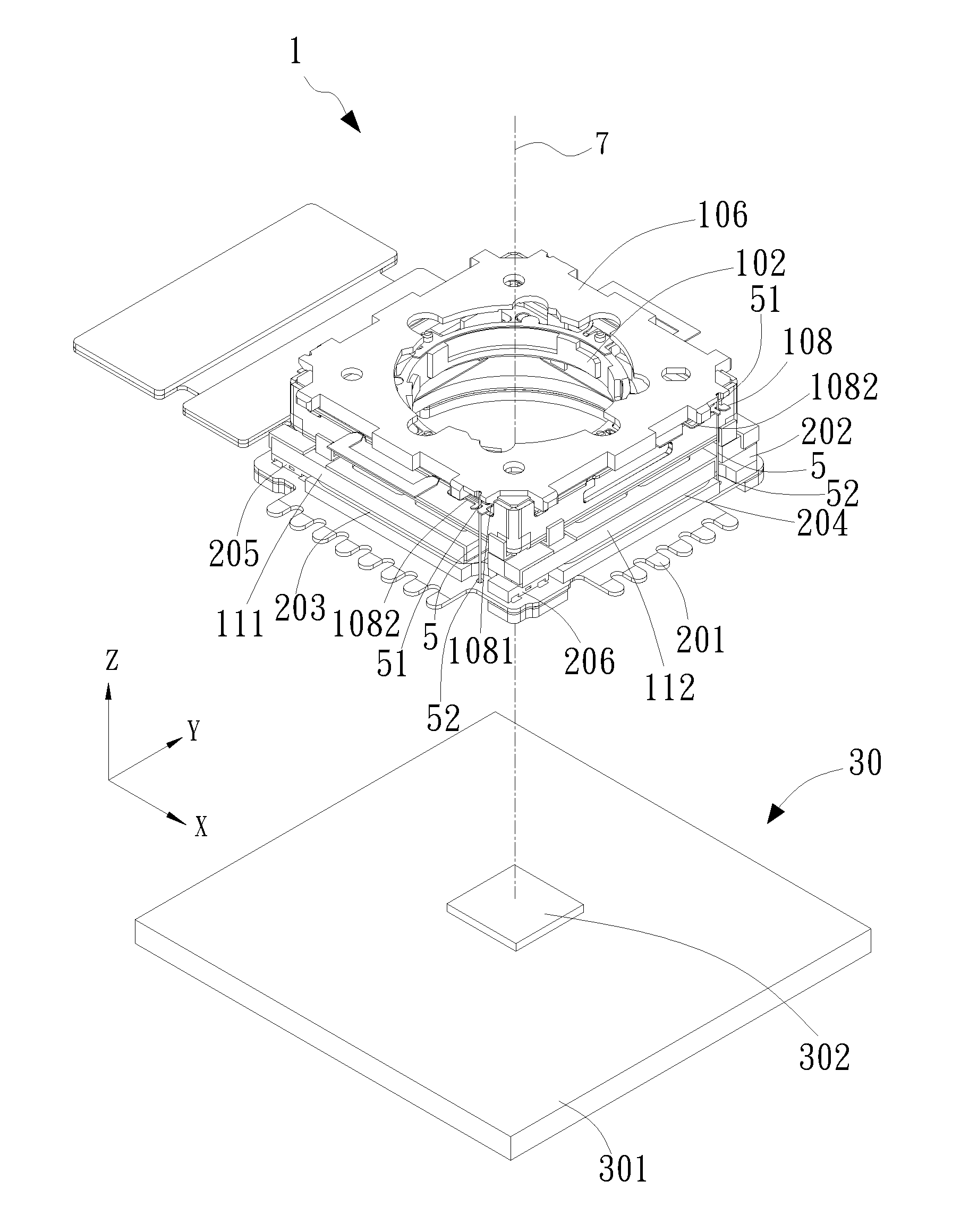
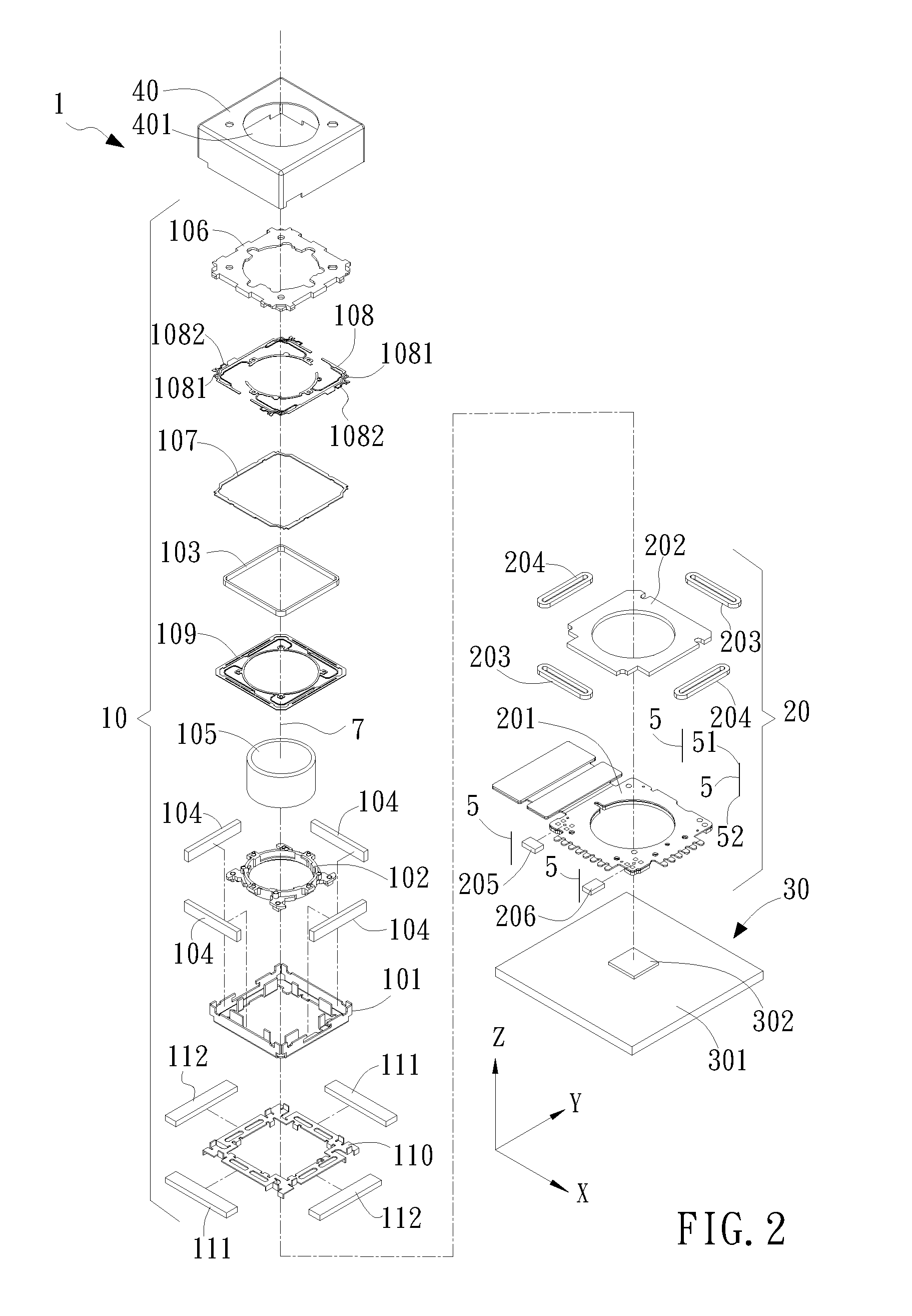
[0028]Please refer to FIGS. 2 and 3 respectively for an exploded perspective view and a partially assembled perspective view of an optical image stabilizer 1 according to the present invention.

[0029]The present invention provides an elastic supporting structure for the optical image stabilizer 1, wherein the optical image stabilizer 1 defines three axial directions that are perpendicular to one another, namely an X-axis direction, a Y-axis direction, and a Z-axis direction. The optical image stabilizer 1 includes a movable portion 10, a compensation module 20, a sensing module 30, and a plurality of first elastic elements 5. In this embodiment, the first elastic elements 5 are a plurality of suspension wires (hence the first elastic elements also referred to hereinafter as the suspension wires 5). The movable portion 10 is an automatic focusing module (hence the movable portion also referred to hereinafter as the automatic focusing module 10) or a zooming module. The movable portion...


PUM


Abstract

An elastic supporting structure for an optical image stabilizer is provided. The optical image stabilizer includes a movable portion, a compensation module, and a plurality of suspension wires. The movable portion is provided therein with a lens. The compensation module corresponds to the movable portion, and both are located on the same image-capturing optical axis. Each suspension wire has two ends respectively connected to the movable portion and the compensation module. The movable portion is provided with an upper spring plate. One end of each suspension wire is connected to a length-increased outer line element and at least one additional auxiliary line element of the upper spring plate, and the other end of each suspension wire is connected to the compensation module, such that the movable portion corresponds to the compensation module and is spaced therefrom by a predetermined distance. Also, anti-shake function performs well with suspension wires.

Description

BACKGROUND OF INVENTION[0001]1. Field of the Invention[0002]The present invention relates to an elastic supporting structure for an optical image stabilizer and, more particularly, to an elastic supporting structure for preventing a lens module from permanent deformation should the lens module be dropped, thereby providing the lens module with enhanced shock resistance.[0003]2. Description of the Prior Art[0004]Digital cameras have been continuously downsized due to the advancement of technology, and thanks to the miniaturization of lens modules, many small electronic devices nowadays, such as mobile phones, are equipped with digital camera functions as a basic requirement. In order to provide automatic focusing or zooming, the microlenses in those electronic devices are typically driven to move by a voice coil motor (VCM), which carries a lens and can move the lens back and forth along an image-capturing optical axis by means of a coil, a magnet and an elastic plate. Moreover, cons...

Claims


Application Information

Patent Timeline
Patent Type & Authority Applications(United States)
IPC IPC(8): G02B27/64
CPCG02B27/646H04N23/687
Inventor WU, FU-YUANHUANG, SHIH-TINGLIN, JYUN-JIE
Owner TDK TAIWAN
Why Eureka
Try Eureka