Artificial joint

a technology of artificial joints and joints, applied in the field of artificial joints, can solve the problems of increasing the torque resistance described above and outweighing the disadvantag

Inactive Publication Date: 2013-08-22
GS DEVMENT
View PDF5 Cites 36 Cited by
  • Summary
  • Abstract
  • Description
  • Claims
  • Application Information

AI Technical Summary

Benefits of technology

[0007]It is an object of the invention to at least partly overcome one or more limitations of the prior art. In particular, it is a

Problems solved by technology

However, examinations have shown that the increased torque resistance descri

Method used


Image

  • Artificial joint
  • Artificial joint
  • Artificial joint

Examples


Embodiment Construction

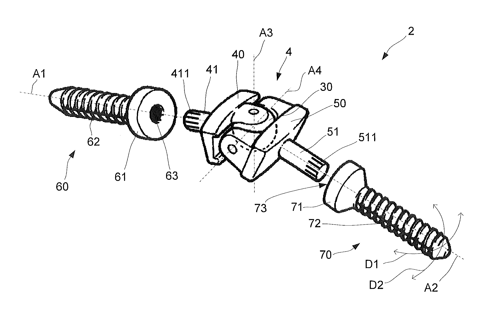
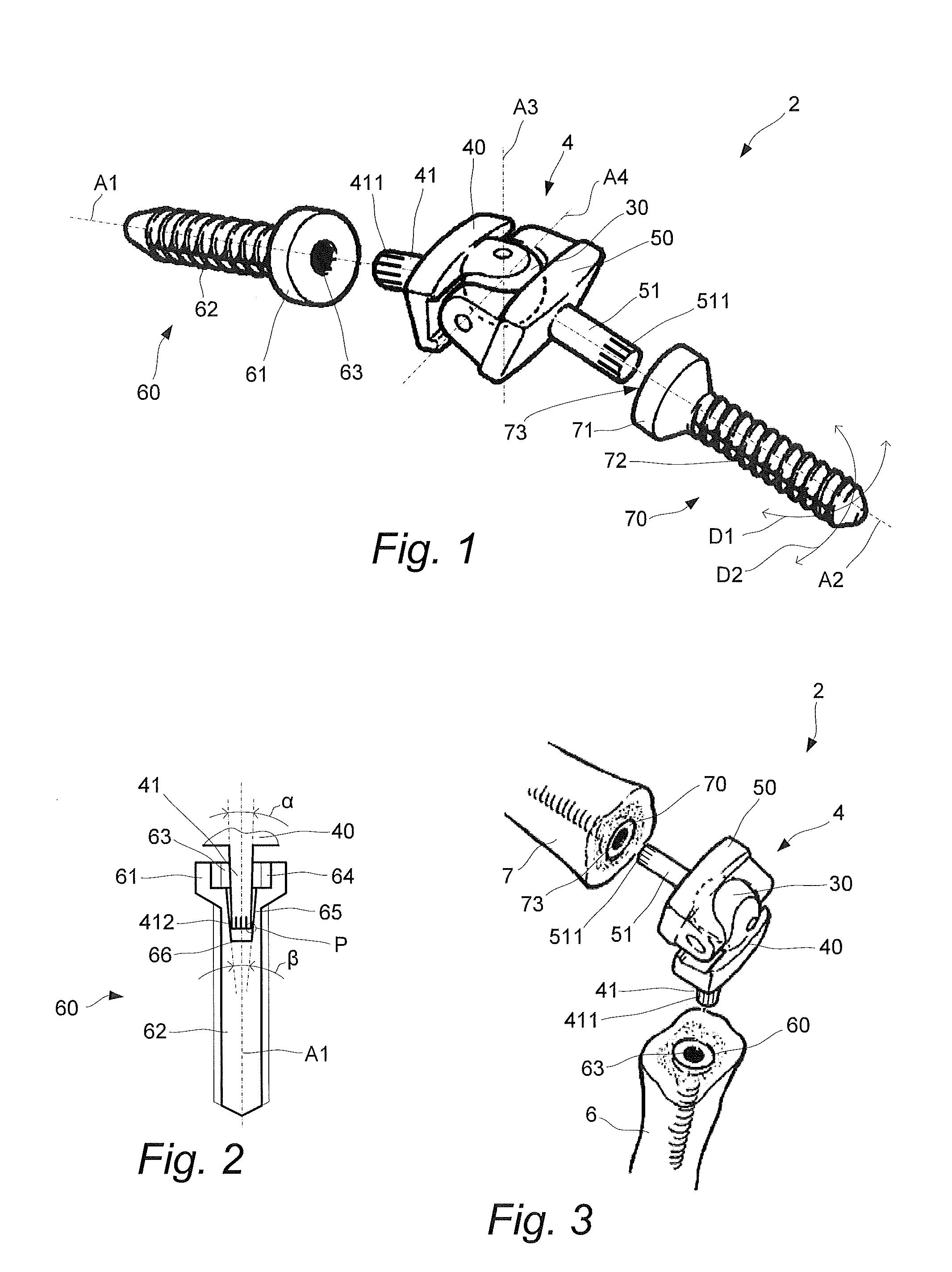
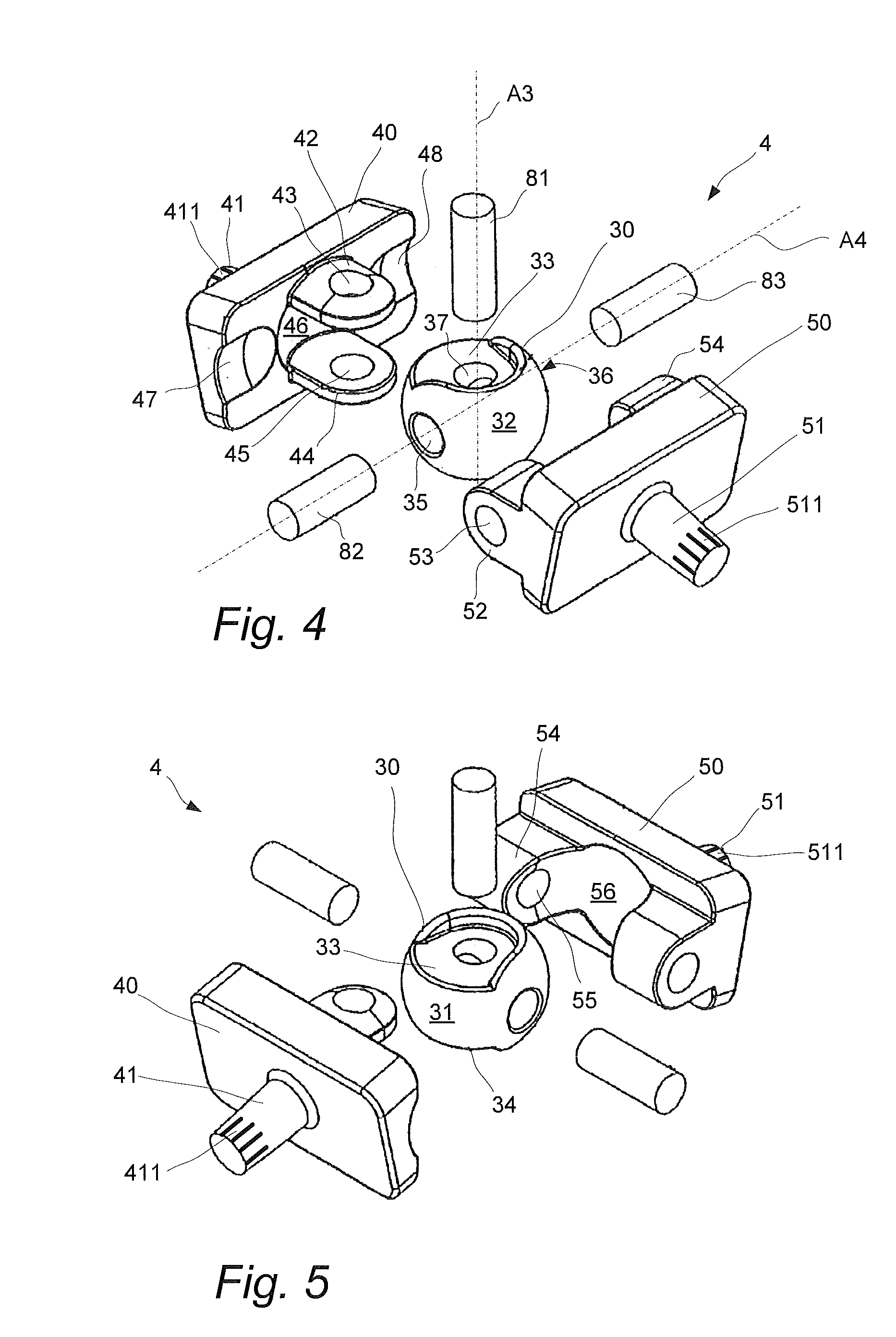
[0022]With reference to FIG. 1 an embodiment of an artificial joint 4 is illustrated. The artificial joint 4 comprises a first base element 40 and a second base element 50 that are pivotally connected to an intermediate body 30. The artificial joint 4 has a first protrusion 41 that extends from the artificial joint 4 along a first geometrical axis A1, and has a second protrusion 51 that extends from the artificial joint 4 along a second geometrical axis A2.

[0023]Specifically, the first protrusion 41 has an elongated shape and extends from the first base element 40. The first protrusion 41 is configured to be press-fitted into a first screw device 60 which in this embodiment has the form of a screw with a head 61 from which an elongated, threaded portion 62 extends. In this context, the first protrusion 41 is configured (i.e. adapted or arranged) to be press-fitted means that it is designed for the specific purpose of being press-fitted. This means that components of known artificial...


PUM


Abstract

An artificial joint comprising a first base element and a second base element that are pivotally connected to an intermediate body. A first protrusion extends from the first base element and is configured to be press-fitted into a screw device that is anchored to a first bone member, and a second protrusion extends from the second base element and is configured to be press-fitted into a screw device that is anchored to a second bone member. A related kit-of-parts is also described.

Description

RELATED APPLICATIONS[0001]This is a U.S. national phase application of PCT / EP2011 / 068980, filed Oct. 28, 2011, which claims priority to Swedish Application No. 1051138-4, filed Oct. 29, 2010, both of which are incorporated herein by reference.TECHNICAL FIELD[0002]The invention relates to an artificial joint that comprises two base elements that are pivotally connected to an intermediate body. The artificial joint is particularly suitable as a surgically implantable prosthetic replacement device for a joint in the fingers, but may also be suitable for joints in toes.BACKGROUND[0003]Today artificial joints are used to replace finger joints like the metacarpophalangeal, proximal interphalangeal and distal interphalangeal joints, for example in case of accidents or diseases such as arthritis. For use to replace toe joints it is in particular the metatarsalphalangeal joint and the proximal phalangeal joints.[0004]Such artificial joints have been known for some time and a number of differ...

Claims


Application Information

Patent Timeline
IPC IPC(8): A61F2/42
CPCA61F2/4225A61F2/4241A61F2002/30347A61F2002/30349A61F2002/4251A61F2002/3085A61F2002/4233A61F2002/4246A61F2002/4248A61F2002/30635A61F2002/30367A61F2002/4243A61F2/30A61F2002/30576
Inventor STAHL WERNERSSON, EVAHAKANSSON, HAKAN
Owner GS DEVMENT
Why Eureka
Try Eureka