Patient positioning support structure

a positioning support and patient technology, applied in the field of patient positioning support structure, can solve the problems of obstructing the movement of c-arm and o-arm mobile fluoroscopic imaging devices, base members, and bulky surgical tables with overhead frame structures

Inactive Publication Date: 2013-08-29
WARSAW ORTHOPEDIC INC
View PDF2 Cites 78 Cited by
  • Summary
  • Abstract
  • Description
  • Claims
  • Application Information

AI Technical Summary

Benefits of technology

[0021]In yet another further embodiment, the apparatus includes a manually operable command actuator for generating a signal representing a desired amount of extension of the lift arms of the angulation subassembly. In some embodiments, the controller includes a microprocessor effected by a computer program to actuate the amount of extension of the lift arms of the angulation subassembly. In some embodiments, the controller includes a manually operable command actuator for generating a signal representing the desired amount of extension of the lift arms of the angulation subassembly. In some embodi...

Problems solved by technology

The enlarged base members associated with such cantilever designs are problematic in that they can and do obstruct the movement of C-arm and O-arm mobile fluoroscopic imaging devices and other equipment.
Surgical tables with overhead frame structures are bulky and may require the use of dedicated operating rooms, since in some cases they cannot be moved easily out of the way.
Neither of these designs is easily portable or storable.
If the patient's trunk, entire upper body and head and neck are not fre...

Method used


Image

  • Patient positioning support structure
  • Patient positioning support structure
  • Patient positioning support structure

Examples


Embodiment Construction

[0045]As required, detailed embodiments of the patient positioning support structure are disclosed herein; however, it is to be understood that the disclosed embodiments are merely exemplary of the apparatus, which may be embodied in various forms. Therefore, specific structural and functional details disclosed herein are not to be interpreted as limiting, but merely as a basis for the claims and as a representative basis for teaching one skilled in the art to variously employ the disclosure in virtually any appropriately detailed structure.

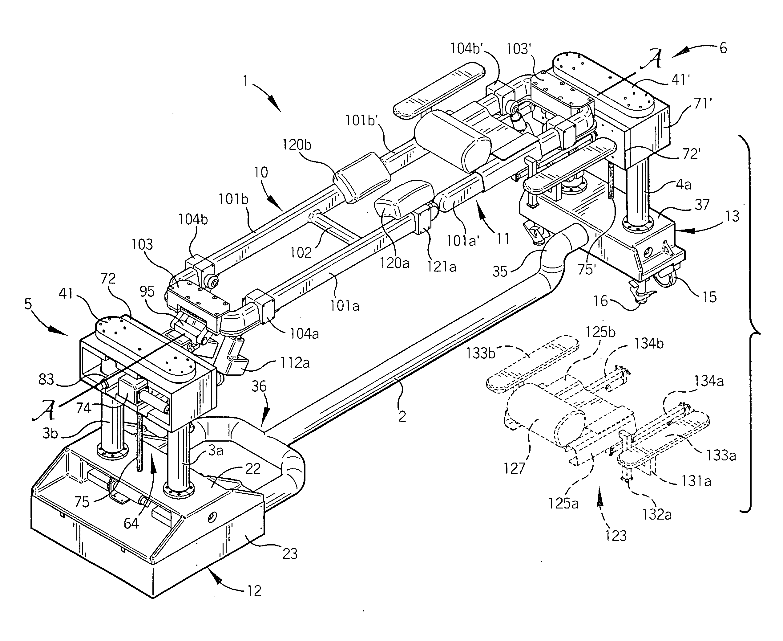
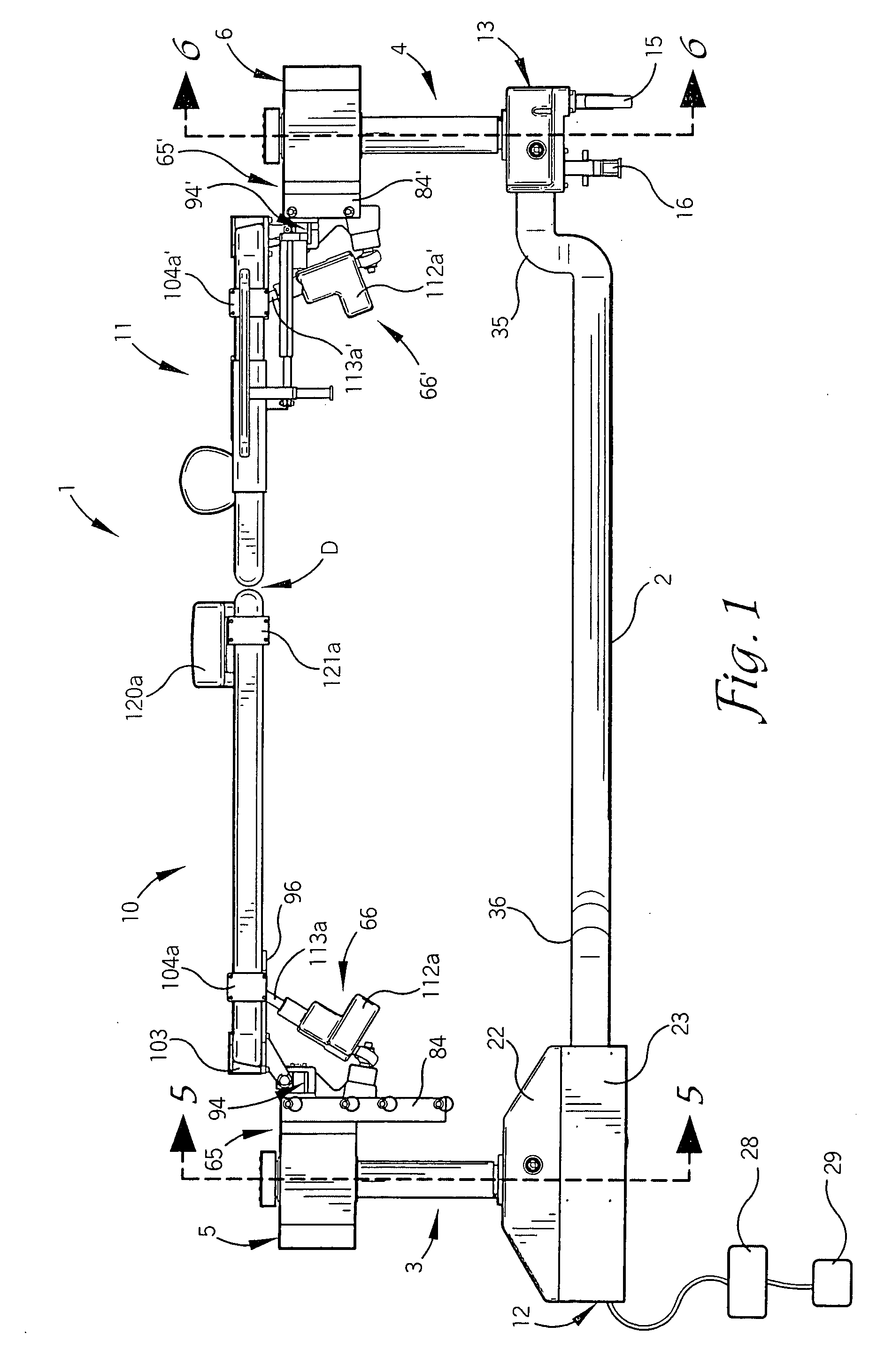
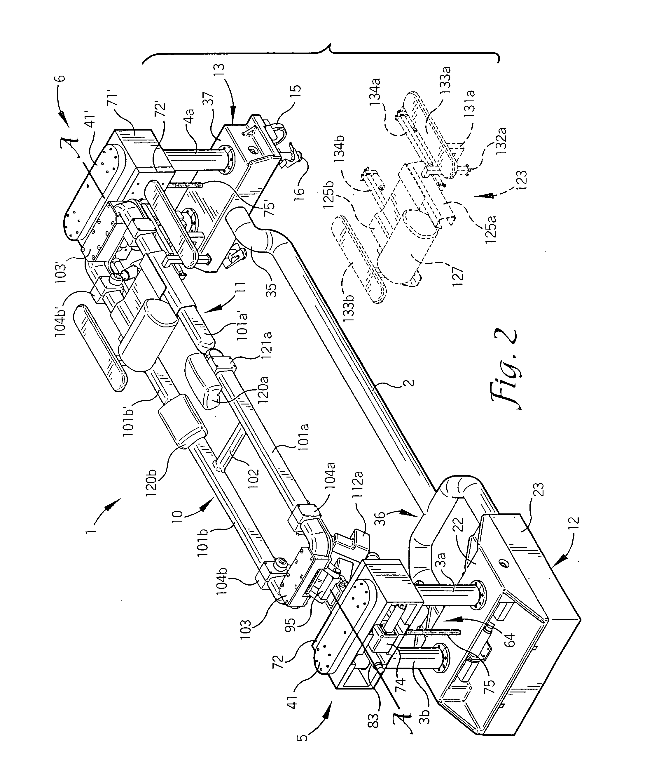
[0046]Referring now to the drawings, an embodiment of a patient positioning support structure according to the disclosure is generally designated by the reference numeral 1 and is depicted in FIGS. 1-12. The structure 1 includes first and second upright end support pier or column assemblies 3 and 4 which are illustrated as connected to one another at their bases by an elongate connector rail or rail assembly 2. It is foreseen that the column supp...


PUM


Abstract

A patient support structure includes a pair of independently height-adjustable supports, each connected to a patient support. The supports may be independently raised, lowered, rolled or tilted about a longitudinal axis, laterally shifted and angled upwardly or downwardly. Position sensors are provided to sense all of the foregoing movements. The sensors communicate data to a computer for coordinated adjustment and maintenance of the inboard ends of the patient supports in an approximated position during such movements. A longitudinal translator provides for compensation in the length of the structure when the supports are angled upwardly or downwardly. A patient trunk translator provides coordinated translational movement of the patient's upper body along the respective patient support in a caudad or cephalad direction as the patient supports are angled upwardly or downwardly for maintaining proper spinal biomechanics and avoiding undue spinal traction or compression.

Description

CROSS-REFERENCE TO RELATED APPLICATION[0001]This application is a continuation of U.S. application Ser. No. 12 / 803,173 filed Jun. 21, 2010, which is a continuation-in-part of U.S. application Ser. No. 12 / 460,702 filed Jul. 23, 2009 which was a continuation of U.S. application Ser. No. 11 / 788,513 filed Apr. 20, 2007, now U.S. Pat. No. 7,565,708, which claimed the benefit of U.S. Provisional Application No. 60 / 798,288 filed May 5, 2006 and which was also a continuation-in-part of U.S. application Ser. No. 11 / 159,494 filed Jun. 23, 2005, now U.S. Pat. No. 7,343,635, which was a continuation-in-part of U.S. application Ser. No. 11 / 062,775 filed Feb. 22, 2005, now U.S. Pat. No. 7,152,261. This application is also a continuation of U.S. application Ser. No. 12 / 803,192 filed Jun. 21, 2010, which is a continuation-in-part of U.S. application Ser. No. 12 / 460,702 filed Jul. 23, 2009 which was a continuation of U.S. application Ser. No. 11 / 788,513 filed Apr. 20, 2007, now U.S. Pat. No. 7,565,7...

Claims


Application Information

Patent Timeline
IPC IPC(8): A61G13/08
CPCA61G13/08A61G13/0036A61G2013/0054A61G13/06A61G13/04A61G13/0054
Inventor JACKSON
Owner WARSAW ORTHOPEDIC INC
Why Eureka
Try Eureka