
External Pressure Testing of Gas Lift Valve in Side-Pocket Mandrel

a gas lift valve and side-pocket technology, which is applied in the direction of survey, instruments, borehole/well accessories, etc., can solve the problems of inability to readily allow external pressure testing on the valve/mandrel pocket interface, prohibitively slow testing, and high cos

Inactive Publication Date: 2013-08-29
WEATHERFORD TECH HLDG LLC
View PDF6 Cites 22 Cited by
  • Summary
  • Abstract
  • Description
  • Claims
  • Application Information

AI Technical Summary

Benefits of technology

The patent text describes a method for installing gas lift valves in a gas lift system used in oil wells. The valves are installed in side-pocket mandrels, which are tubing string components that are positioned in the wellhead. The valves allow gas to flow from the annulus (between the tubing string and the casing) to the tubing string, while preventing gas from flowing back to the annulus. The valves are tested using a gas lift valve testing system, which involves injecting gas into the annulus and observing the flow of gas in the tubing string. The technical effect of the patent text is to provide a method for installing gas lift valves in a gas lift system that ensures proper functionality and performance.

Problems solved by technology

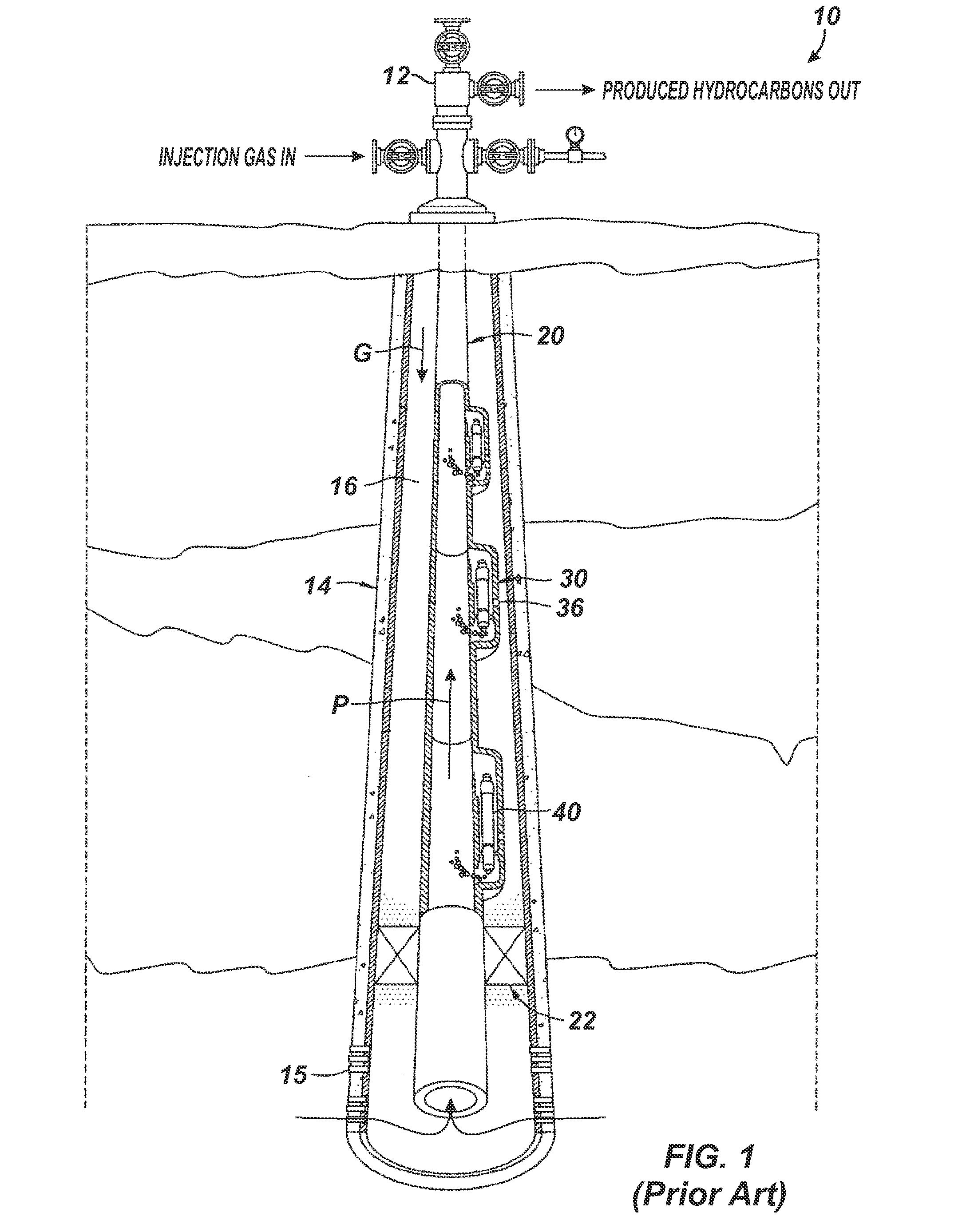
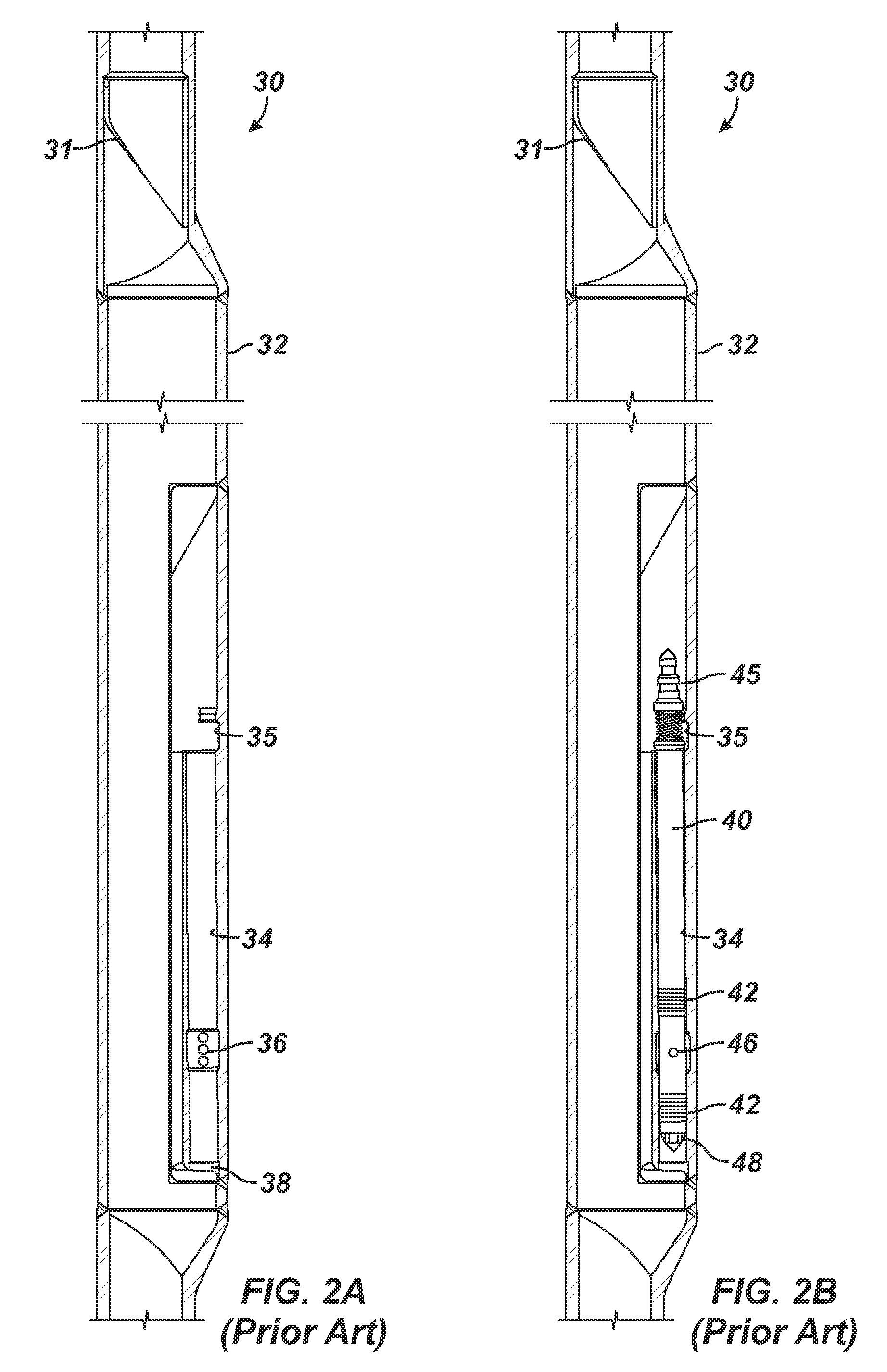
If the valve 40 is not properly installed, pressure losses will occur because the valve 40 has not properly sealed off the side ports 36.
Unfortunately, the side-pocket mandrels 30 do not readily allow external pressure testing to be performed on the valve / mandrel pocket interfaces before deployment.
As expected, this form of testing is prohibitively slow, expensive, and cumbersome and is even more so when performed in the field.
However, several potential problems may not be detected if the interface between the valve 40 and the mandrel's pocket 34 is not externally pressure tested.
Second, the internal pressure test does not indicate whether the external-pressure containing seals (i.e., the elements for holding pressure from the annulus) are actually capable of holding pressure.
By then, remedies to the problems are very expensive and complicated.

Method used


Image

  • External Pressure Testing of Gas Lift Valve in Side-Pocket Mandrel
  • External Pressure Testing of Gas Lift Valve in Side-Pocket Mandrel
  • External Pressure Testing of Gas Lift Valve in Side-Pocket Mandrel

Examples


Embodiment Construction

[0049]As noted previously, gas lift valves positioned in side-pocket mandrels may not be completely installed, and internal pressure tests may not be capable of revealing that the valves are not completely installed in the mandrels before deployment due to the difficulties in implementing such a test in the field or even in a workshop. To actually test the installation of the gas lift valves in the mandrel, an external pressure test is preferably performed. Currently, operators do not externally pressure test side-pocket mandrels before deployment. To that end, a system and method are disclosed herein that allow operators to perform an external pressure test and evaluate the installation of gas lift valves in the side-pocket mandrels.

[0050]Before discussing how external pressure testing can be performed to achieve the purposes disclosed herein, discussion first turns to a gas lift system, gas lift valve, and side-pocket mandrel according to the present disclosure.

[0051]A. Gas Lift S...


PUM


Abstract

A side-pocket mandrel is used for a gas lift system. The mandrel has two external ports, which can use external check valves when deployed downhole. Before installing the mandrel, operators preferably pressure test the interface of a gas lift valve in the pocket of the mandrel. Internal pressure testing is performed. The mandrel, however, is suited for external-pressure testing, which is impractical for other types of side-pocket mandrels. In the external pressure test, a pressure test line is coupled to the inlet port on the mandrel, which is already threaded in a reinforced area of the mandrel to receive a check valve. The other inlet port is closed off with a plug or with a check valve. When external pressure is applied with the test line, operators can determine if the gas lift valve is properly seated (i.e., whether the latch is properly engaged in the pocket). Operators can also determine if the seals between the gas lift valve and the pocket are capable of holding external pressure.

Description

CROSS-REFERENCE TO RELATED APPLICATIONS[0001]This application claims the benefit of U.S. Provisional Appl. 61 / 602,721, filed 24 Feb. 2012, which is incorporated herein by reference in its entirety.FIELD OF THE DISCLOSURE[0002]The subject matter of the present disclosure is directed to artificially lifting fluid from a wellbore using a gas lift system, and more particularly, to testing the installation of gas lift valves in mandrels of a gas lift system.BACKGROUND OF THE DISCLOSURE[0003]Operators use gas lift valves in side-pocket mandrels to lift produced fluids in a well to the surface. The gas lift valves allow gas from the tubing annulus to enter the tubing through the valve, while preventing flow from the tubing to the annulus.[0004]1. Gas Lift System[0005]A typical gas lift system 10 illustrated in FIG. 1 has a wellhead 12 atop a casing 14 that passes through a formation. A tubing string 20 positioned in the casing 14 has a number of side-pocket mandrels 30 and a production pac...

Claims


Application Information

Patent Timeline
Patent Type & Authority Applications(United States)
IPC IPC(8): E21B43/12G01M3/02
CPCG01M3/02E21B43/123E21B34/105E21B23/03E21B47/117
Inventor RAE, COLIN GORDON
Owner WEATHERFORD TECH HLDG LLC
Learn More