
Mobile terminal and wireless charging module therefor

a wireless charging and mobile terminal technology, applied in the field of mobile terminals, can solve the problems of inability to develop satisfactory levels of capacity of batteries, inability to view video or television programs, and inability to provide contact terminals to outsides of charging units, etc., to achieve the effect of reducing heat generation and increasing charging efficiency

Inactive Publication Date: 2013-08-29
LG ELECTRONICS INC
View PDF2 Cites 30 Cited by
  • Summary
  • Abstract
  • Description
  • Claims
  • Application Information

AI Technical Summary

Benefits of technology

The patent text describes a mobile terminal that can improve wireless charging efficiency and reduce heat generation when using induive coupling. It also aims to reduce heat caused by eddy currents during wireless charging.

Problems solved by technology

However, batteries having a satisfactory level of capacity have not been developed yet despite continuing research.
As a result, unless a charging operation is performed by determining a proper charging time and method based on a residual battery amount, mobile terminals may often fail to allow user to view video or television programs.
However, the contact terminals provided to outsides of the charging unit and the battery are not desirable in terms of appearance.
Moreover, if they are exposed to moisture, the charged energy may be lost, and a charging operation may not be properly performed due to an inferior contact status.
In the non-contact charging method using inductive coupling, however, the secondary coil causes a magnetic flux density to quickly reach a saturated state in the case of wireless charging because the shield sheet is formed in a simple rectangular shape, and the magnetic flux generates eddy currents in the shield sheet to disturb a change in magnetic field.
Therefore, unsaturated magnetic fields of the secondary coil (reception coil) are all lost after the magnetic flux density reaches the saturated state, whereby wireless charging efficiency is reduced, and the temperature of the shield sheet rises due to the eddy currents.

Method used


Image

  • Mobile terminal and wireless charging module therefor
  • Mobile terminal and wireless charging module therefor
  • Mobile terminal and wireless charging module therefor

Examples


Embodiment Construction

[0040]Description will now be given in detail of the exemplary embodiments, with reference to the accompanying drawings. For the sake of brief description with reference to the drawings, the same or equivalent components will be provided with the same reference numbers, and description thereof will not be repeated.

[0041]Hereinafter, a mobile terminal according to the present invention will be explained in more detail with reference to the attached drawings. The suffixes attached to components of the wireless speaker, such as ‘module’ and ‘unit or portion’ were used for facilitation of the detailed description of the present invention. Therefore, the suffixes do not have different meanings from each other.

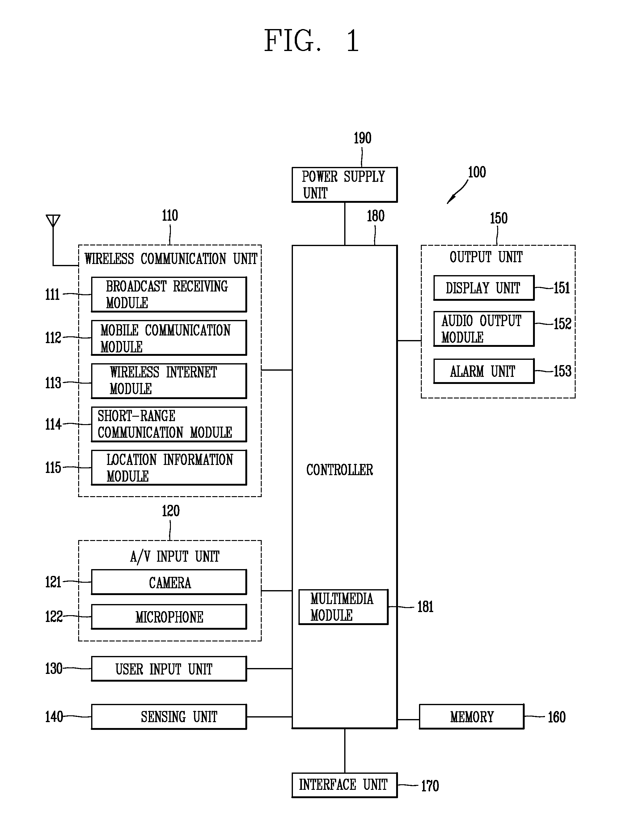
[0042]A terminal may be implemented in various types. For instance, the terminal in the present description includes a mobile terminal such as a portable phone, a smart phone, a notebook computer, a digital broadcasting terminal, Personal Digital Assistants (PDA), Portable Multimedi...


PUM


Abstract

The present invention provides a mobile terminal which, when wireless (contactless) charging of a battery is performed by approximating a transmission coil of a charging unit (charging pad) and a reception coil provided in a wireless charging module of a mobile terminal, can adjust the saturation magnetic flux density and eddy currents of a shield sheet to which the reception coil is attached, the shield sheet being provided in the wireless charging module. When the reception coil is placed on the shield sheet to perform wireless charging, the saturation magnetic flux density and eddy current generation in the shield sheet are adjusted for wireless charging purpose because a part of the region in which the magnetic flux density is most quickly saturated was clipped off from the shield sheet. Thus, charging efficiency can be increased, and the problem of heat generation of the shield sheet can be effectively.

Description

CROSS-REFERENCE TO RELATED APPLICATION[0001]Pursuant to 35 U.S.C. §119(a), this application claims the benefit of earlier filing date and right of priority to Korean Application No. 10-2012-0018670, filed on Feb. 23, 2012, the contents of which is incorporated by reference herein in its entirety.BACKGROUND OF THE INVENTION[0002]1. Field of the Invention[0003]The present disclosure relates to a mobile terminal which can improve wireless charging efficiency and reduce heat generation by adjusting the saturation magnetic flux density and eddy currents of a shield sheet, and particularly, to a wireless charging module therefor.[0004]2. Background of the Invention[0005]Recently, mobile terminals allowing users to receive broadcast or multicast signals to view video or television programs have created the demand for higher-capacity batteries. However, batteries having a satisfactory level of capacity have not been developed yet despite continuing research. As a result, unless a charging o...

Claims


Application Information

Patent Timeline
Patent Type & Authority Applications(United States)
IPC IPC(8): H02J7/00
CPCH02J7/025H02J5/005H02J7/00045H02J50/90H02J50/70H02J50/10H04B5/26H04B5/79H04B1/3883H02J7/0048H02J7/02
Inventor KIM, YOUNGTAEHAN, KIWONCHONG, KABSUNGYI, MIZI
Owner LG ELECTRONICS INC
Features
  • Generate Ideas
  • Intellectual Property
  • Life Sciences
  • Materials
  • Tech Scout
  • Unparalleled Data Quality
  • Higher Quality Content
  • 60% Fewer Hallucinations
Learn More