Current sensor

a current sensor and current technology, applied in the field of current sensors, can solve the problems of insufficient reduction of hysteresis and offset of output signals, and achieve the effect of reducing hysteresis

Active Publication Date: 2013-08-29
ALPS ALPINE CO LTD
View PDF7 Cites 0 Cited by
  • Summary
  • Abstract
  • Description
  • Claims
  • Application Information

AI Technical Summary

Benefits of technology

[0020]In this configuration, annealing in a magnetic field in the stripe width direction of the magnetoresistive element is not required in the manufacturing process of the magnetoresistive element. Therefore, the induced magnetic anisotropy in the...

Problems solved by technology

In contrast, a current sensor including magnetoresistive elements has a problem in that an offset occurs in an output signal due to the hysteresis in...

Method used


Image

  • Current sensor
  • Current sensor
  • Current sensor

Examples


Embodiment Construction

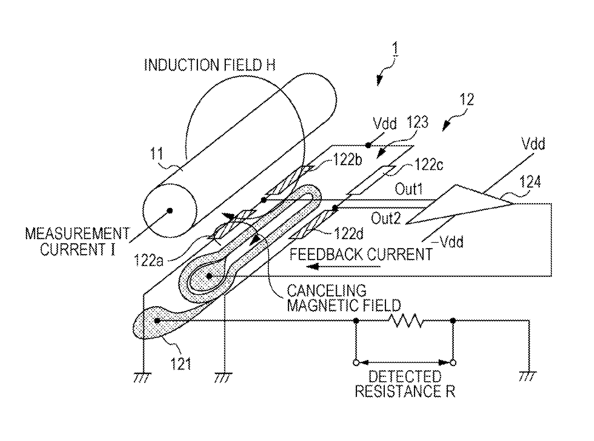
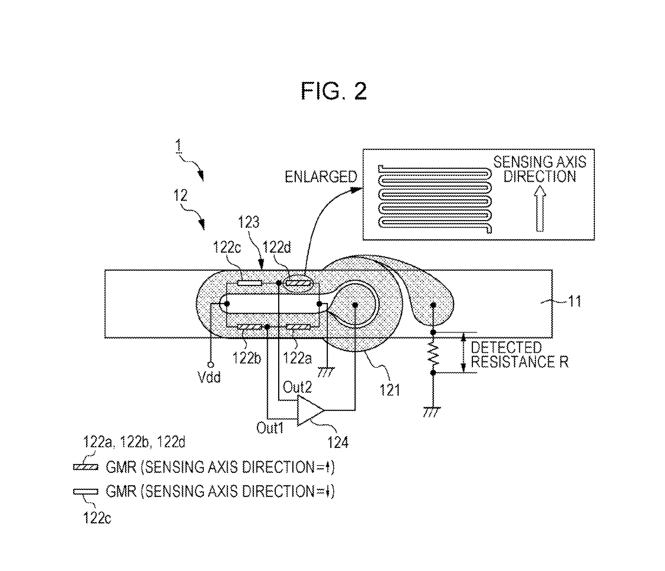
[0029]Further improvement of measurement accuracy in a current sensor including magnetoresistive elements requires a reduced hysteresis in a magnetoresistive element, and also requires that the zero-field resistance values (R0) and the temperature coefficients of resistance (TCR0) in a zero magnetic field agree among the elements in a full-bridge circuit which is constituted by four elements such as magnetoresistive elements.

[0030]In a current sensor including magnetoresistive elements, a hard bias layer is formed to provide uniaxial anisotropy for a free magnetic layer, enabling reduction in hysteresis. In contrast, when a hard bias layer and a free magnetic layer are stacked one on top of the other, a contact portion which is in the free magnetic layer and with which the hard bias layer is in contact is strongly and firmly magnetized to form a dead zone for the external magnetic field. Therefore, this dead zone makes it difficult to reduce the hysteresis.

[0031]When a portion of a ...


PUM


Abstract

A current sensor includes a magnetoresistive element that has a stripe shape and that has a sensing axis in a certain direction. The magnetoresistive element includes element portions that are disposed so as to be spaced apart from each other in a longitudinal direction of the stripe shape, and permanent magnet portions, each of which is disposed between adjacent ones of the element portions. Each element portion has a layered structure including a free magnetic layer whose magnetization direction is changed with respect to an external magnetic field, a non-magnetic intermediate layer, and a ferromagnetic pinned layer whose magnetization direction is pinned. The permanent magnet portion includes a hard bias layer, and an electrode layer that is disposed so as to cover the hard bias layer.

Description

CLAIM OF PRIORITY[0001]This application is a Continuation of International Application No. PCT / JP2011 / 073220 filed on Oct. 7, 2011, which claims benefit of Japanese Patent Application No. 2010-245291 filed on Nov. 1, 2010. The entire contents of each application noted above are hereby incorporated by reference.BACKGROUND OF THE INVENTION[0002]1. Field of the Invention[0003]The present invention relates to current sensors that measure the magnitude of a current, and more particularly, to a current sensor including magnetoresistive elements.[0004]2. Description of the Related Art[0005]Heretofore, in the fields of, for example, electric cars and solar batteries, a current sensor including magnetic detection devices which output an output signal due to an induction field caused by a measurement current has been used. An example of a magnetic detection device included in such a current sensor is a magnetoresistive element such as a giant magnetoresistive (GMR) element.[0006]A GMR element...

Claims


Application Information

Patent Timeline
IPC IPC(8): G01R19/00
CPCB82Y25/00G01R15/205G01R19/00H01L43/08G01R33/093H10N50/10B82Y5/00G11B3/00H01F1/00
Inventor IDE, YOSUKESAITO, MASAMICHITAKAHASHI, AKIRAICHINOHE, KENJINISHIYAMA, YOSHIHIRO
Owner ALPS ALPINE CO LTD
Why Eureka
Try Eureka