Color signal processing device
- Summary
- Abstract
- Description
- Claims
- Application Information
AI Technical Summary
Benefits of technology
Problems solved by technology
Method used
Image
Examples
first embodiment
1. First Embodiment
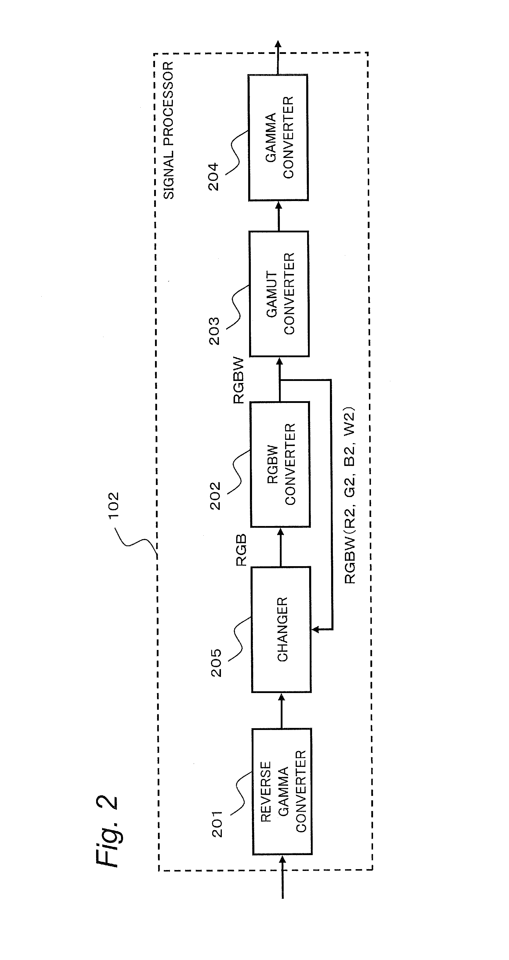
[0034]In a first embodiment, when there is a pixel of which color indicated by a color signal converted from the RGB signal into the RGBW signal is a color outside of a displayable color gamut of a display unit, the brightness of an input image is decreased by decreasing the gain of the RGB signal for the region of the entire image, so that color saturation caused by conversion of the color into a color outside of the displayable color gamut is prevented. In particular, the gain is decreased not only for the pixel which is to be converted into a color outside of the displayable color gamut but also for pixels around the pixel to be converted into a color outside of the displayable color gamut. As a result, the signal level can be decreased without diversifying the color shade between the pixel which is suppressed in color saturation and the pixels around the pixel suppressed in color saturation, so that natural color representation in appearance is achieved.
1.1. C...
second embodiment
2. Second Embodiment
[0135]In the first embodiment, when the RGBW signal contains a color outside of the displayable color gamut, the gain for the entire image region is decreased. However, the image region for which the color saturated pixel is detected and the gain is decreased does not need to be the entire image but only needs to be a region which contains pixels of a color outside of the displayable color gamut. Therefore, in the second embodiment, a configuration of detecting the color saturated pixel and controlling the gain for each of some regions (blocks) of the image region instead of a configuration of detecting the color saturated pixel and decreasing the gain for the entire image region will be described.
[0136]Specifically, in the second embodiment, the entire image is divided into a plurality of blocks (for example, regions of 10 in the lateral direction and 6 in the longitudinal direction) and the gain value is controlled based on the RGB signals for the pixels contai...
third embodiment
3. Third Embodiment
[0185]In the first and second embodiments, the current RGB signal is corrected by using the gain factors calculated from the signal values of the RGBW signal which is processed and generated before in terms of time. That is, the gain for the input RGB signal is corrected by using the feedback control of the RGBW signal.
[0186]However, the idea of the present disclosure is not limited to the configuration using the feedback control, and the feedfoward control may be used. Then, in the third embodiment, a configuration of calculating the gain factor by using the feedforward control will be described. Note that the same components as those of the first embodiment are denoted by the same reference letters and the description of them will be omitted.
[0187]The signal processor according to the third embodiment will be described with reference to a drawing. FIG. 12 is a diagram illustrating a configuration of the signal processor 102c according to the third embodiment.
[01...
PUM
 Abstract
Description
Claims
Application Information
 - R&D
- Intellectual Property
- Life Sciences
- Materials
- Tech Scout
- Unparalleled Data Quality
- Higher Quality Content
- 60% Fewer Hallucinations
Browse by: Latest US Patents, China's latest patents, Technical Efficacy Thesaurus, Application Domain, Technology Topic, Popular Technical Reports.
© 2025 PatSnap. All rights reserved.Legal|Privacy policy|Modern Slavery Act Transparency Statement|Sitemap|About US| Contact US: help@patsnap.com


