Manual Dosing Device

a dosing device and manual technology, applied in the field of manual dosing devices, can solve the problems of reducing the selection of usable materials, affecting the selection of materials, so as to reduce the stress on the housing, and facilitate the selection

Active Publication Date: 2013-08-29
EPPENDORF SE
View PDF3 Cites 7 Cited by
  • Summary
  • Abstract
  • Description
  • Claims
  • Application Information

AI Technical Summary

Benefits of technology

[0027]The support structure of the manual dosing device according to the invention is an elongated frame. The means for releasably holding the syringe or pipette tip are arranged on the frame. They can be a part of the frame or attached to it. The drive means are attached to the frame. The means for releasably holding and the drive means are connected to each other by displacement means. In a version the displacement means are means for transmitting the movement generated by the drive means to the syringe plunger of a syringe. To this end, the displacement means are releasably connected to means for releasably holding the syringe plunger. When the drive means generate a linear drive movement, the transmission means can be a rod that is drivable by the drive means and is connected to means for releasably holding the syringe plunger and that is axially guided on the frame. A positive displacement dosing device is thereby realized. In the other versions, the displacement means are a displacement unit for displacing a column of air. The displacement unit is preferably a cylinder and the plungers displaceable therein. The cylinder is connected to the means for releasably holding via a channel with a hole to the means for releasably holding that communicate with the top tip opening of a pipette tip when the means for releasably holding hold a pipette tip. The displacement unit is fixed to the frame. When designed as a cylinder with a plunger that is displaceable therein, the cylinder is fixed to the frame. An air cushion dosing device is thereby realized. The amount of drawn and released liquid is set by the amount which the plunger or air column is displaced by the displacement means. With an air cushion dosing device having a cylinder and displaceable plunger therein, the displacement means preferably have a plunger rod that is connected to the plunger and has a pushbutton on the top end and a return spring which presses against the frame, or against the plunger rod or pushbutton. The return spring presses the plunger upward into a home position from which air can be ejected from the displacement device by actuating the pushbutton against the effect of the return spring.
[0028]When the drive means drive the displacement means, forces are introduced into the frame. If the displacement means are transmission means for transmitting movement to a syringe plunger, these forces are transmitted by the drive means and means for releasably holding the syringe flange to the frame. When the displacement means are a displacement unit, these forces act between the drive means and the frame as well as between the displacement unit and the frame. These forces depend especially on the amount and viscosity of the liquid to be dosed. The frame is designed so that it does not significantly deform under the exerted forces. This ensures that the movable elements of the displacement means are reproducibly moved with the desired precision. The desired dosing precision is thereby achieved. The forces acting when the syringe or pipette tip is connected to the manual dosing device are also absorbed by the frame. The frame is preferably made of a polyether ketone (PEEK) that is distinguished by its enormous stability. The housing is preferably only mounted to the frame at a few points to relieve stress on the housing. The housing is preferably guided in a longitudinal direction on the frame and fixed at a few positions (such as only one or two positions) so that the frame can extend or retract in the longitudinal direction with reference to the housing without transmitting significant force to the housing. Consequently, the force arising during use can be substantially absorbed by the frame, thus relieving stress on housing.
[0029]The particular properties of the frame give the designer greater freedom in selecting the housing materials and designing and dimensioning the housing. It is in particular possible to use soft housing materials and design and dimension the housing such that the haptics of the manual dosing device are particularly pleasant. The design with a frame therefore makes it possible to use a particularly soft housing with improved haptics. The frame only partially supports the housing; in particular, the areas of the housing that are not supported are designed to be particularly easily shapable which is perceived as tactically pleasant by the user holding such a manual dosing device in his hand. The special properties of the frame make it possible to also use housing materials that have a special chemical resistance, and / or are dirt repellent, and / or can be easily cleaned, and / or are more easily processable, and / or are particularly economical. Forces introduced into the housing by the hand of the user, especially when actuating the control elements of the manual dosing device, are captured by a large area and transferred to the frame so that the housing is not overloaded. Another advantage is that using a frame as a support structure makes it possible to pre-mount the components of the manual dosing device on the frame and test the manual dosing device before the housing is attached. In addition, the design according to the invention of the manual dosing device makes it easier to use carryover parts (COPs) in different manual dosing devices. In particular, different manual dosing devices can be provided with the same frame which is equipped with different components depending on the product. The different products may optionally be differentiated by a different housing.
[0030]According to one embodiment, the frame has a plurality of frame parts that are joined and firmly connected with each other. Dividing the frame into a plurality of frame parts makes it possible to separately premount components on different frame parts and thereby prepare assemblies. In addition, differently arranged manual dosing devices can be partially designed with equal respectively similar frame parts and partially with different frame parts. According to a preferred embodiment, the frame has a bottom part and top part. The bottom part of the frame is preferably equipped with the means for releasably holding a syringe or pipette tip, and the top part is preferably equipped with drive means and displacement means.

Problems solved by technology

This restricts the selection of usable materials.
The disadvantage of known manual dosing devices is that the housing does not sit well in the hand, easily becomes dirty and is difficult to clean.

Method used


Image

  • Manual Dosing Device
  • Manual Dosing Device
  • Manual Dosing Device

Examples


Embodiment Construction

[0055]While this invention may be embodied in many different forms, there are described in detail herein a specific preferred embodiment of the invention. This description is an exemplification of the principles of the invention and is not intended to limit the invention to the particular embodiment illustrated

[0056]In this patent application, the terms “bottom” and “top” refer to the preferred alignment of the manual dosing device when dosing in which the elongated housing is vertically aligned, and the syringe or pipette tip is arranged below the housing.

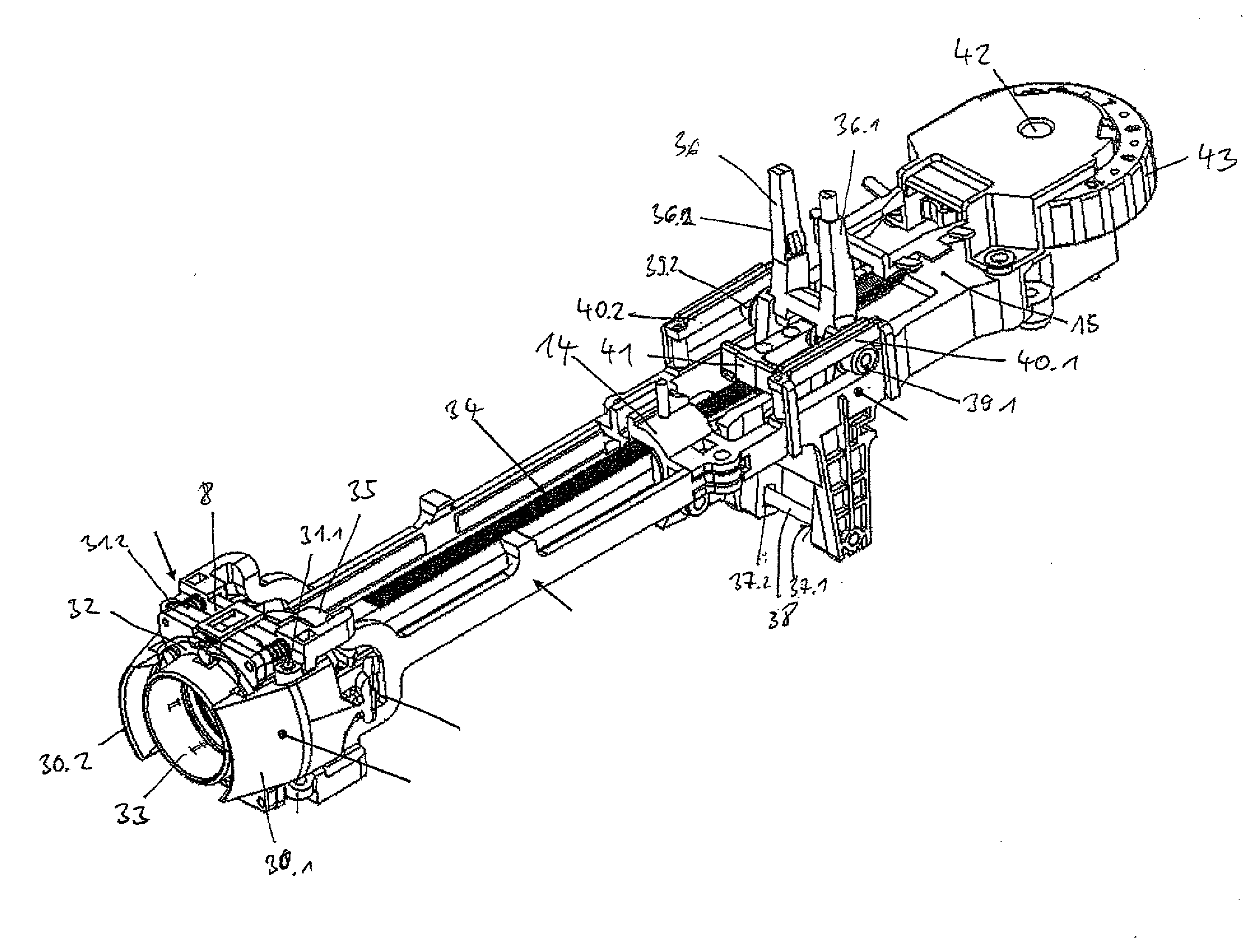
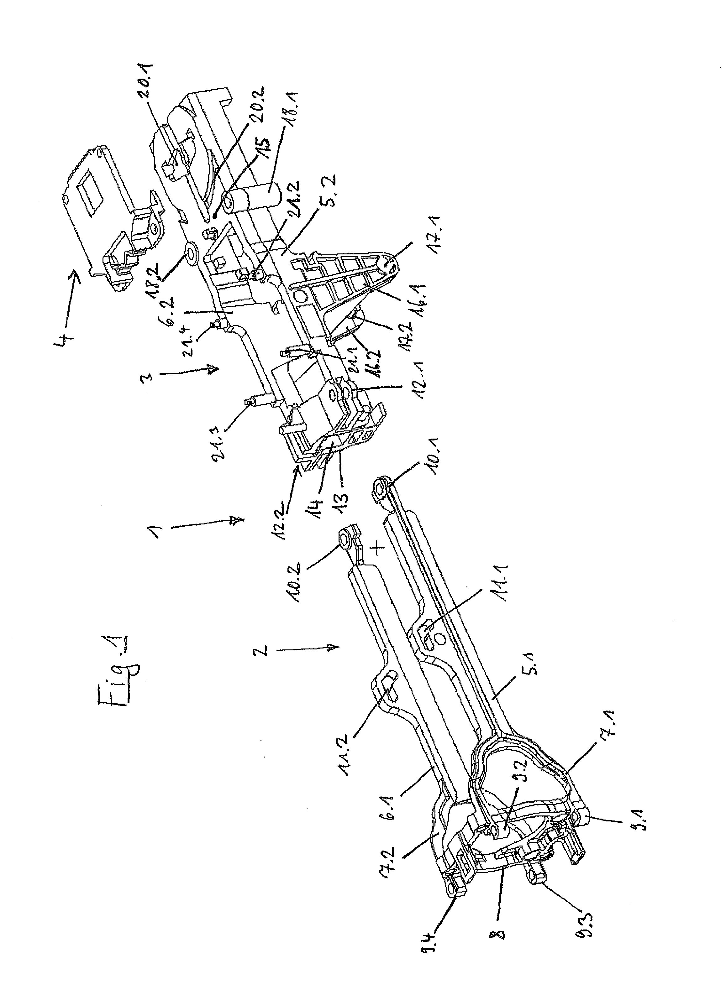
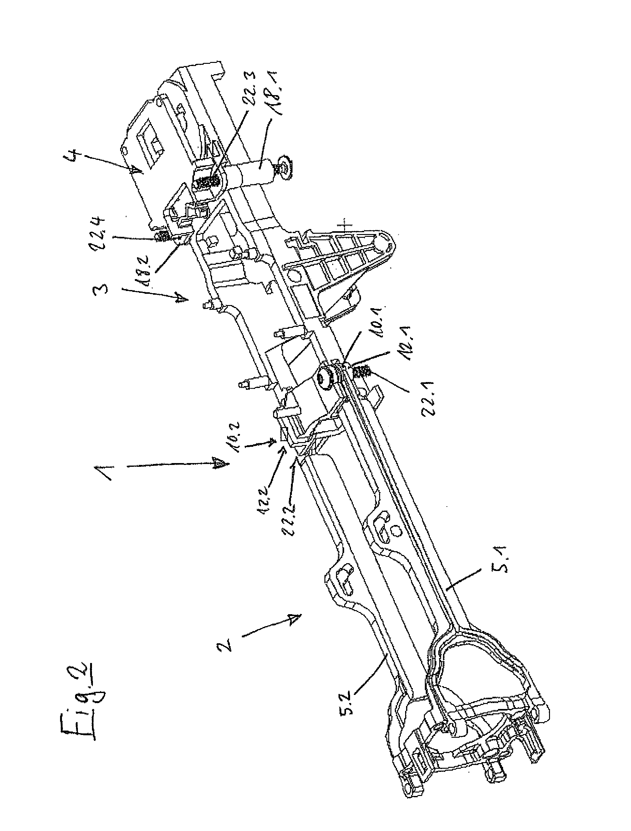
[0057]The manual dosing device shown in FIGS. 1 to 6 is a dispenser, i.e., a positive displacement dosing device by means of which a syringe can be emptied in a plurality of steps.

[0058]According to FIG. 1, the frame 1 comprises a bottom part 2 and a top part 3. The top part 3 is assigned a cover 4 to hold a dial.

[0059]The bottom part comprises two parallel, strip-shaped longitudinal members 5.1, 6.1. These are connected at the bo...


PUM


Abstract

A manual dosing device comprising
    • an elongated frame as a support structure,
    • means for releasably holding a syringe or pipette tip at the bottom end of the frame,
    • drive means that are attached above the means for releasably holding to the frame,
    • displacement means for displacing a fluid in the syringe or pipette tip that can be driven by the drive means and are connected to the means for releasably holding, and
    • a housing encasing the frame.

Description

CROSS-REFERENCE TO RELATED APPLICATIONS[0001]Not applicable.STATEMENT REGARDING FEDERALLY SPONSORED RESEARCH[0002]Not applicable.BACKGROUND OF THE INVENTION[0003]The invention relates to a manual dosing device for dosing liquids.[0004]Manual dosing devices are dosing devices for dosing liquids on which a syringe or pipette tip can be releasably held. Syringes have a syringe cylinder with a syringe plunger which can move therein, and an opening connecting the syringe cylinder to the environment for drawing and releasing liquid. The opening is generally arranged in a tip on the floor of the syringe cylinder. Pipette tips are small tubes that generally narrow downward and have a bottom tip opening for drawing and releasing liquid, and a top tip opening to be connected with a displacement device for air. Manual dosing devices are held in one hand by the user while dosing so that the syringe, or pipette tip, held thereon can be aligned with a vessel or another object from which liquid is...

Claims


Application Information

Patent Timeline
Patent Type & Authority Applications(United States)
IPC IPC(8): B01L3/02
CPCB01L3/0217B01L3/0234B01L3/021B01L2300/12B01L2200/12
Inventor REICHMUTH, BURKHARDT
Owner EPPENDORF SE
Why Eureka
Try Eureka