Miniature shredding tool for use in medical applications and methods for making

a technology of miniature shredding and medical applications, applied in the field of micro- and millimeter-scale shredding devices, can solve the problems of destructive separation of masking materials from substrates, and achieve the effects of improving blades, reducing unintended outflow, and improving positional stabilization

Inactive Publication Date: 2013-08-29
CHILDRENS HOSPITAL MEDICAL CENT CINCINNATI +2
View PDF6 Cites 15 Cited by
  • Summary
  • Abstract
  • Description
  • Claims
  • Application Information

AI Technical Summary

Benefits of technology

[0044]It is an object of some embodiments of the invention to provide an improved micro-scale or millimeter scale shredding device for use in medical procedures with (1) improved positional stabilization while operating in a working region, (2) improved blades for disrupting or shredding a material that is to be removed; and / or (3) reduced unintended outflow of shredded material from the shredding device back into the working region outside of the shredding device.
[0046]It is an object of some embodiments of the invention to provide an improved medical procedures (e.g. minimally invasive procedures) involving use of a microscale or millimeter scale shredding device having (1) improved positional stabilization while operating in a working region, (2) improved blades for disrupting or shredding a material that is to be removed; and / or (3) reduced unintended outflow of shredded material from the shredding device back into the working region outside of the shredding device.
[0058]A fifth aspect of the invention provides a microscale or millimeter scale shredding tool for use in a medical procedure, including: (a) a housing having a distal end and a proximal end; (b) a first multi-blade blade stack mounted for rotational motion about a first axis relative to the housing and extending in part from the housing; wherein the housing includes a shroud that result in the first blade stacks being shielded around at least one half of its periphery to provide for reduced outflow of shredded material than if the shielding extended around less than one half their periphery, wherein the shredding tool provides for intake and shredding of material encountered during the medical procedure.
[0063]Another variation of the first variations of the fourth-sixth aspects of the invention include: (i) the first multi-blade blade stack comprising a plurality of first circular blades with first cutting elements extending from circumferences of the first circular blades, (ii) the second multi-blade blade stack comprising a plurality of second circular blades with second cutting elements extending from circumferences of the second circular blades, (iii) each of the first circular blades rotating about a first common axis, (iv) each of the first circular blades rotating about a second common axis, (v) the first circular blades each having a first thickness and a first gap relative to an immediate neighboring first circular blade, (vi) the second circular blades each having a second thickness and a second gap relative to an immediate neighboring second circular blade, and (vii) the first thickness relative to the second gap and the second thickness relative to the first gap allowing interlacing and movement of the first and second blades while providing for intake and shredding of material encountered by the blades during the medical procedure.
[0068]An eighth aspect of the invention provides a medical procedure including: (a) insertion of a microscale or millimeter scale shredding tool into a working area with a body of a patient, comprising: (i) a housing having a distal end and a proximal end; and (ii) a first multi-blade blade stack mounted for rotational motion about a first axis relative to the housing and extending in part from the housing, wherein the housing includes a shroud that result in the first blade stacks being shielded around at least one half of its periphery to provide for reduced outflow of shredded material than if the shielding extended around less than one half their periphery, (b) powering on the drive mechanism and moving the shredding tool to desired locations within the working area to intake and shred selected material; and (c) extracting the shredding tool from the working area and from the body of the patient.
[0073]Another variation of the first variations of the seventh-ninth aspects of the invention provide: (i) the first multi-blade blade stack comprising a plurality of first circular blades with first cutting elements extending from circumferences of the first circular blades, (ii) the second multi-blade blade stack comprising a plurality of second circular blades with second cutting elements extending from circumferences of the second circular blades, (iii) each of the first circular blades rotating about a first common axis, (iv) each of the first circular blades rotating about a second common axis, (v) the first circular blades each having a first thickness and a first gap relative to an immediate neighboring first circular blade, (vi) the second circular blades each having a second thickness and a second gap relative to an immediate neighboring second circular blade, and (vii) the first thickness relative to the second gap and the second thickness relative to the first gap allowing interlacing and movement of the first and second blades while providing for intake and shredding of material encountered by the blades during the medical procedure.

Problems solved by technology

The CC mask plating process is distinct from a “through-mask” plating process in that in a through-mask plating process the separation of the masking material from the substrate would occur destructively.

Method used


Image

  • Miniature shredding tool for use in medical applications and methods for making
  • Miniature shredding tool for use in medical applications and methods for making
  • Miniature shredding tool for use in medical applications and methods for making

Examples


Embodiment Construction

[0100]Electrochemical Fabrication in General

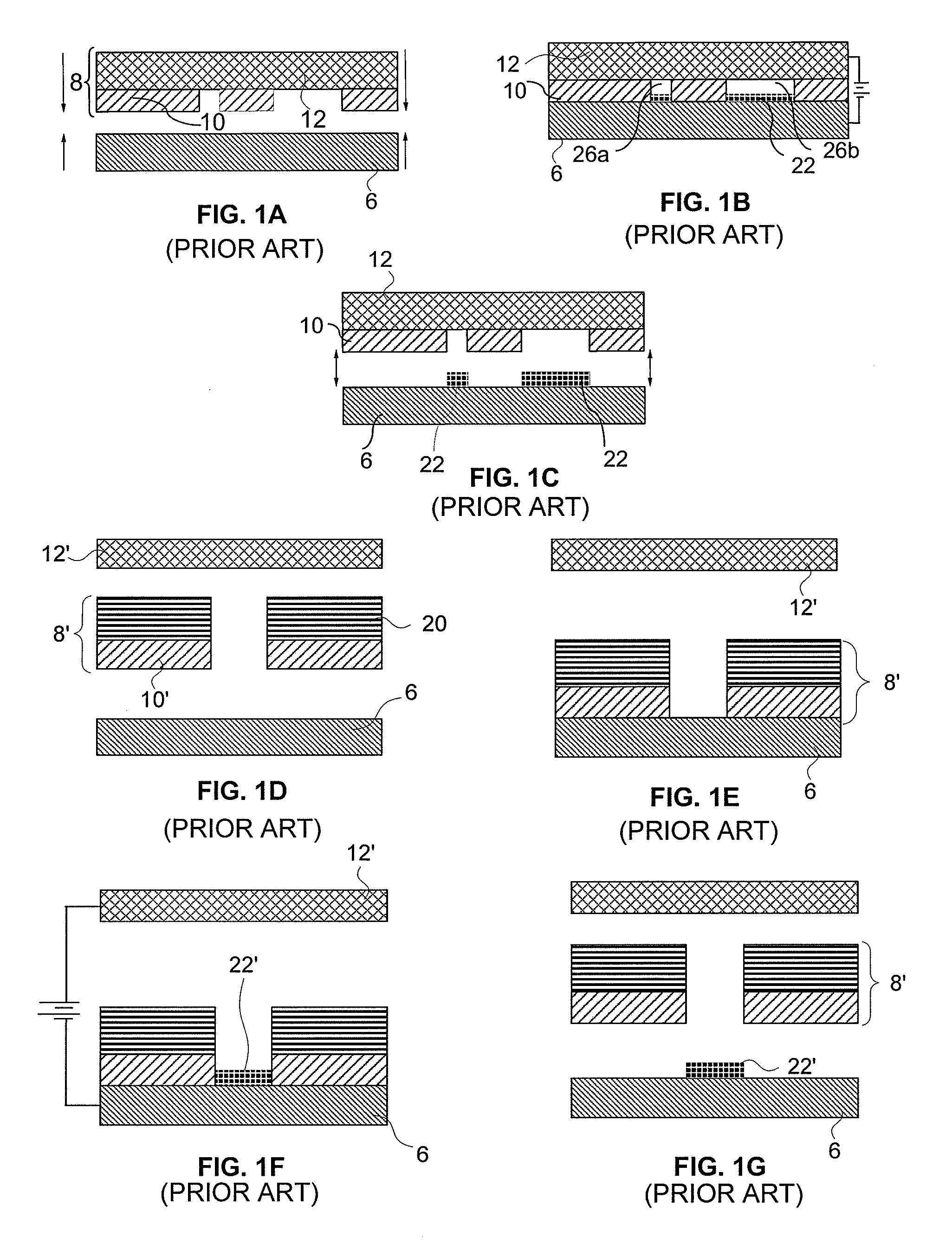
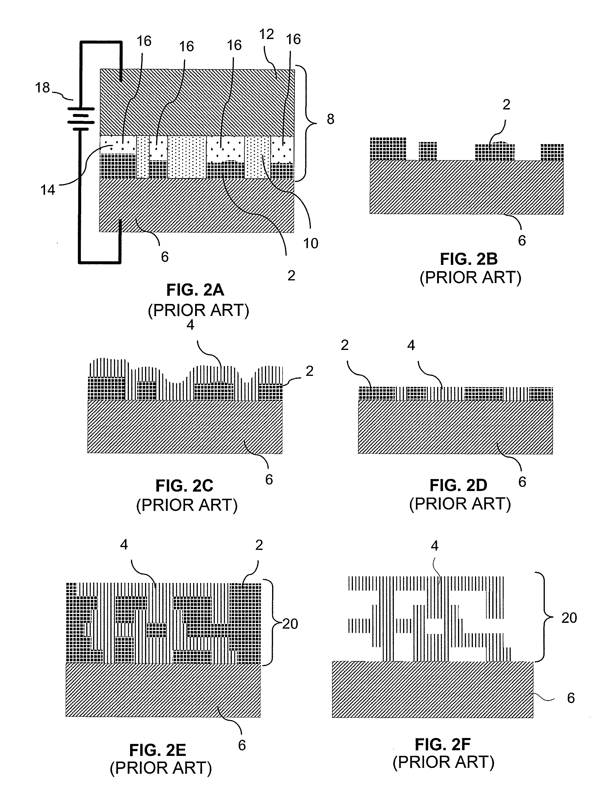
[0101]FIGS. 1A-1G, 2A-2F, and 3A-3C illustrate various features of one form of electrochemical fabrication. Other electrochemical fabrication techniques are set forth in the '630 patent referenced above, in the various previously incorporated publications, in various other patents and patent applications incorporated herein by reference. Still others may be derived from combinations of various approaches described in these publications, patents, and applications, or are otherwise known or ascertainable by those of skill in the art from the teachings set forth herein. All of these techniques may be combined with those of the various embodiments of various aspects of the invention to yield enhanced embodiments. Still other embodiments may be derived from combinations of the various embodiments explicitly set forth herein.

[0102]FIGS. 4A-4I illustrate various stages in the formation of a single layer of a multi-layer fabrication process where ...


PUM


Abstract

The present invention relates generally to the field of micro-scale or millimeter scale devices and to the use of multi-layer multi-material electrochemical fabrication methods for producing such devices with particular embodiments relate to shredding devices and more particularly to shredding devices for use in medical applications. In some embodiments, tissue removal devices include tissue anchoring projections, improved blade configurations, and / or shields or shrouds around the cutting blades to inhibit outflow of tissue that has been brought into the device.

Description

CROSS REFERENCE TO RELATED APPLICATIONS[0001]This application is a divisional of U.S. application Ser. No. 12 / 491,220 filed on Jun. 24, 2009 which claims benefit of U.S. Provisional Patent Application No. 61 / 075,007 filed Jun. 24, 2008; U.S. application Ser. No. 12 / 491,220 filed on Jun. 24, 2009 is a continuation-in-part of U.S. patent application Ser. No. 12 / 490,295 filed Jun. 23, 2009; the '295 application in turn claims benefit of U.S. Provisional Application Nos. 61 / 075,006, filed Jun. 23, 2008; 61 / 164,864, filed Mar. 30, 2009; and 61 / 164,883, filed Mar. 30, 2009. Each of these applications is incorporated herein by reference as if set forth in full herein.U.S. GOVERNMENT RIGHTS[0002]At least a portions of the inventions disclosed and claimed herein were made with government support under Grant No. R01 HL087797 awarded by the National Institute of Health. The Government has certain rights in these inventions.INCORPORATION BY REFERENCE[0003]All publications and patent application...

Claims


Application Information

Patent Timeline
Patent Type & Authority Applications(United States)
IPC IPC(8): A61B17/14
CPCA61B10/02A61B2017/320064A61B17/221A61B17/32002A61B17/320725A61B17/320758A61B19/5212A61B2017/003A61B2017/00327A61B2017/00526A61B2017/00539A61B2017/00553A61B2017/2212A61B2017/2215A61B2017/320048A61B2017/320775A61B17/141A61B17/1671A61B90/361A61B17/14
Inventor LOCKARD, MICHAEL S.FRODIS, URICOHEN, ADAM L.CHEN, RICHARD T.DUPONT, PIERRE E.DEL NIDO, PEDRO J.VASILYEV, NIKOLAY V.
Owner CHILDRENS HOSPITAL MEDICAL CENT CINCINNATI
Why Eureka
Try Eureka