
Supporting Device for a Curved Mirror

Inactive Publication Date: 2013-09-05
THYSSENKRUPP STEEL EURO AG
View PDF12 Cites 3 Cited by
  • Summary
  • Abstract
  • Description
  • Claims
  • Application Information

AI Technical Summary

Benefits of technology

The present invention provides a support device for a curved mirror that is simple and cost-effective. This allows for the production of a low-cost curved mirror.

Problems solved by technology

However, owing to the wedge-like shaping, the securing, for example, to a longitudinal carrier which is provided on the parabolic channeled mirror, is not possible in a simple and precise manner.
Finally, it is also disadvantageous that the connection elements on the parabolic channeled mirror cannot be readily replaced since they are integrated in the support arm.
The use of separate support elements is further difficult with the known support device of a parabolic channeled mirror.

Method used


Image

  • Supporting Device for a Curved Mirror
  • Supporting Device for a Curved Mirror
  • Supporting Device for a Curved Mirror

Examples


Embodiment Construction

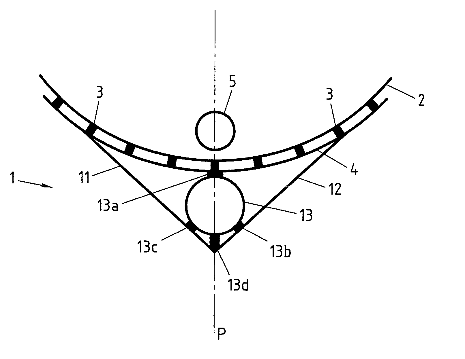
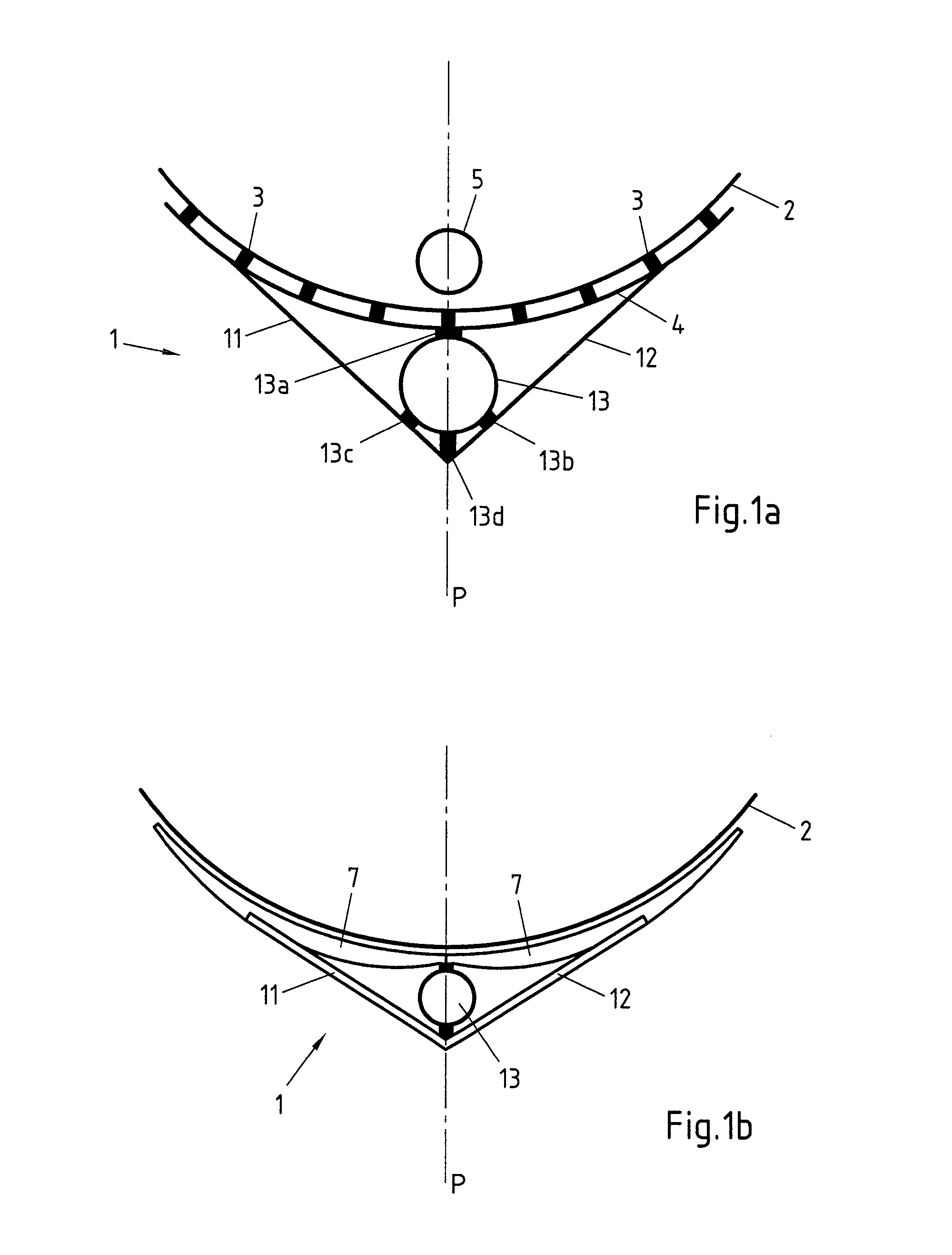
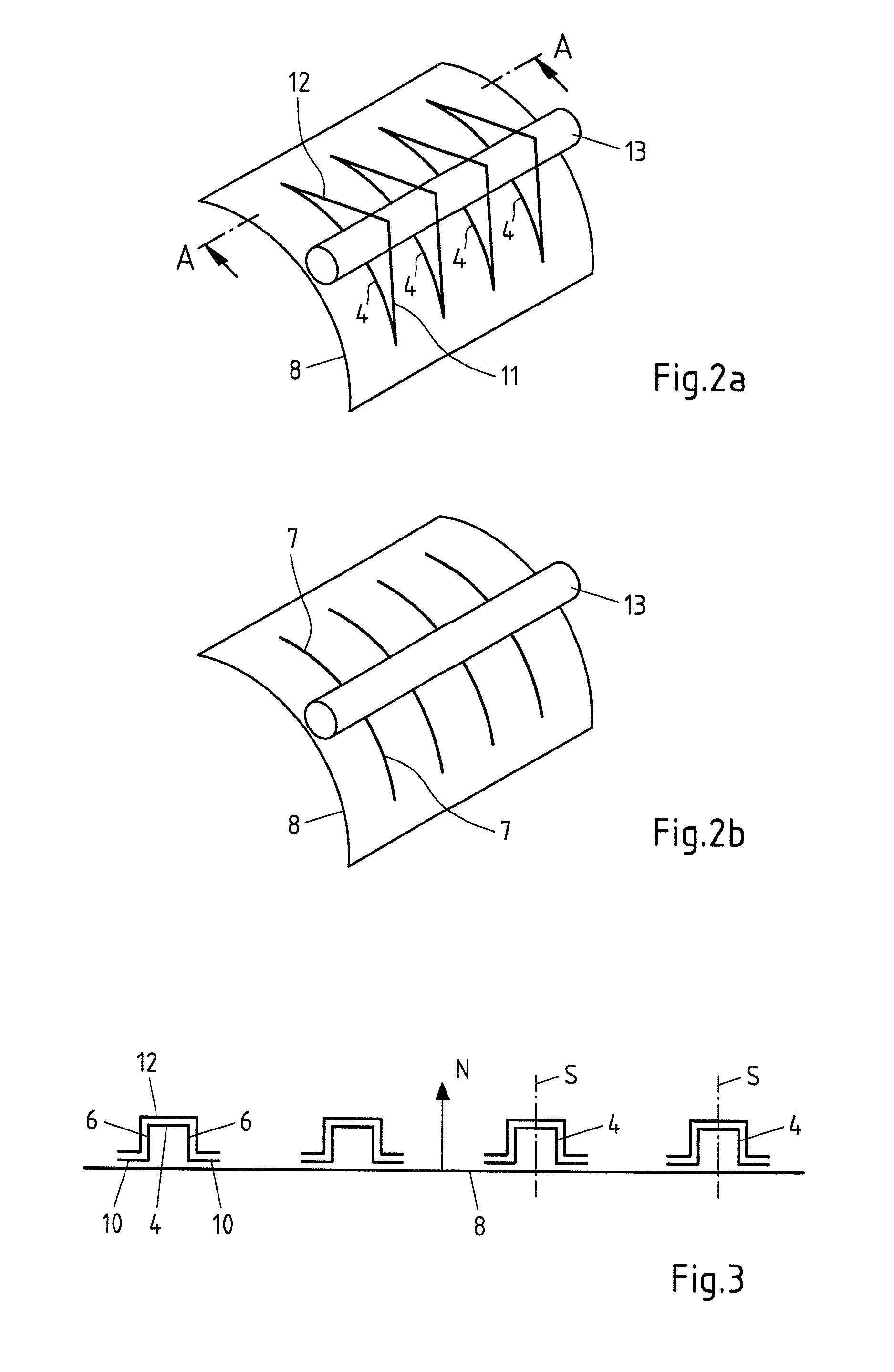
[0029]First, FIG. 1a) is a sectioned view of an embodiment of a support device 1 according to the invention of a curved mirror 2, which is constructed in this instance as a parabolic channeled mirror. The support device 1 additionally has support elements 3 which are in contact with the curved mirror 2 and support it. The support elements 3 are arranged on a U-shaped carrier profile-member 4 which is schematically illustrated in FIG. 1. The support elements 3 may be provided directly by the U-shaped carrier profile-member 4 or by separate support elements 3. There is arranged in the centre of the parabolic channeled mirror 2 an absorber pipe 5, on which the incident rays of the sun are focused and in which a medium to be heated flows. Furthermore, both FIG. 1a) and FIG. 1b) show a mirror axis P which indicates the mirror-symmetrical structure of the support device 1 extending in the longitudinal direction of the parabolic channeled mirror. Owing to the structure which is axially or ...


PUM


Abstract

The invention relates to a support device for a curved mirror having support elements and a curved mirror. The objective of providing a support device for a curved mirror which is constructed in a particularly simple manner and which enables particularly low production costs is achieved by a support device in that the support device has at least one bent metal carrier profile-member, the bent carrier profile-member having in the longitudinal direction an at least similar curvature to the curved mirror and being substantially mirror-symmetrical in the longitudinal direction.

Description

CROSS-REFERENCE TO RELATED PATENT APPLICATIONS[0001]This patent application is a continuation of PCT / EP2011 / 067736, filed Oct. 11, 2011, which claims priority to German Application No. 102010060091.1, filed Oct. 20, 2010, the entire teachings and disclosure of which are incorporated herein by reference thereto.FIELD OF THE INVENTION[0002]The invention relates to a support device for a curved mirror having support elements and a curved mirror.BACKGROUND OF THE INVENTION[0003]In order to encourage the development of renewable energy sources, the central issue concerns not only questions to be addressed relating to increasing the energy yield, but also increasingly the reduction of the necessary investment costs. In solar-thermal installations having a plurality of mirrors, the usable mirror surface-area determines the achievable power output of a solar-thermal power station. Solar-thermal power stations are provided with flat mirrors, but also with curved mirrors, for example, with pa...

Claims


Application Information

Patent Timeline
IPC IPC(8): G02B7/182F24S23/71F24S23/74
CPCF24J2/14F24J2/5233F24J2/5403F24J2002/5215F24J2002/522G02B7/182G02B5/10G02B7/183Y02E10/45Y02E10/47F24J2002/5224F24S23/71F24S23/74F24S25/13F24S30/42F24S2025/801F24S2025/804F24S2025/806Y02E10/40
Inventor DREWES, STEPHANGRO ERUSCHKAMP, THOMASHILFRICH, ERIKHIRT, MARKLIESNER, JENSPATBERG, LOTHARGLASS, ROMAN
Owner THYSSENKRUPP STEEL EURO AG
Learn More