
Coating method and coating apparatus

Inactive Publication Date: 2013-09-05
TOYOTA JIDOSHA KK
View PDF0 Cites 11 Cited by
  • Summary
  • Abstract
  • Description
  • Claims
  • Application Information

AI Technical Summary

Benefits of technology

The patent describes a problem with the width of coating film during battery production. A new method and apparatus are needed to form a coating film of uniform width. The technical effect is to improve the yield of battery production and to simplify the coating process.

Problems solved by technology

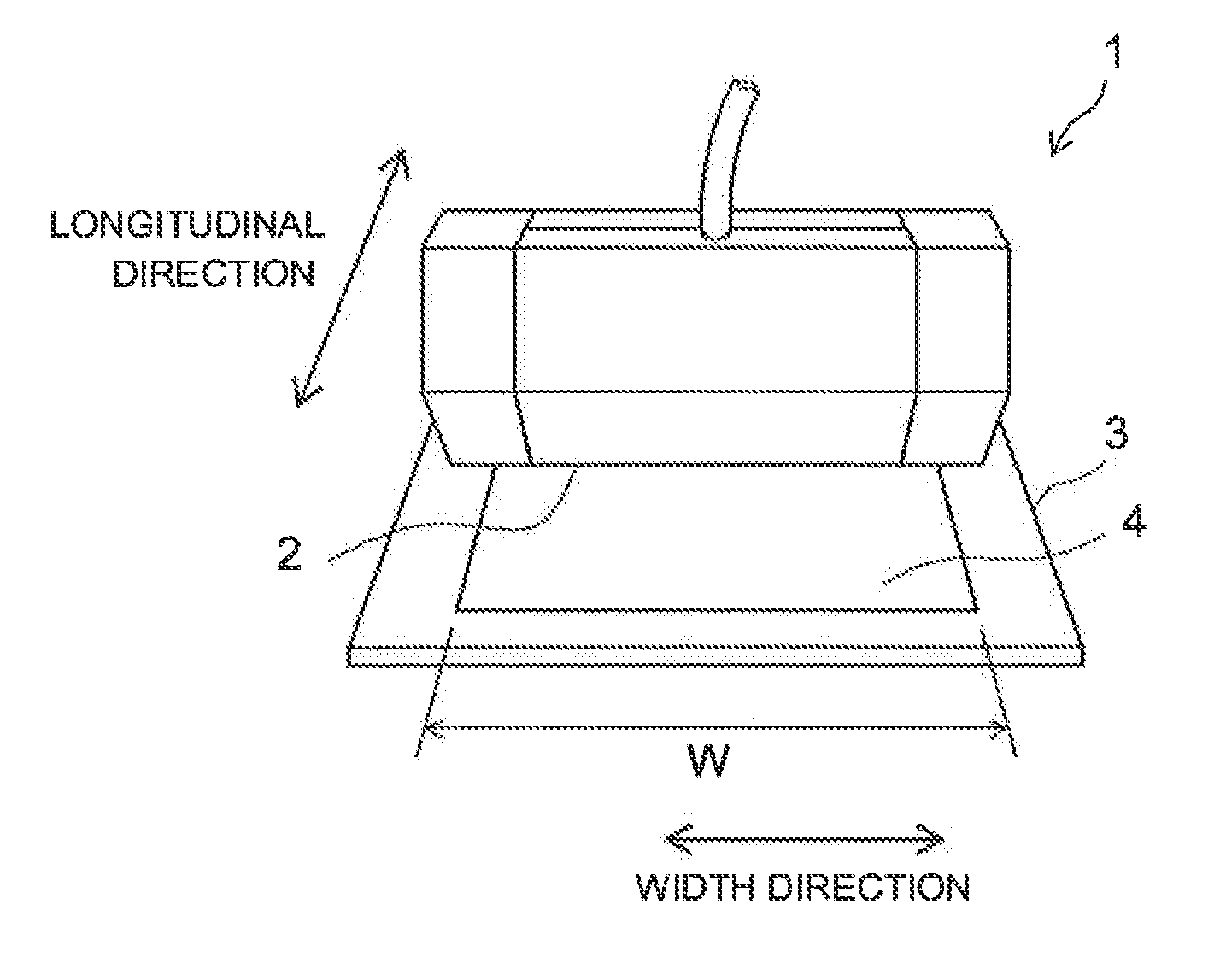
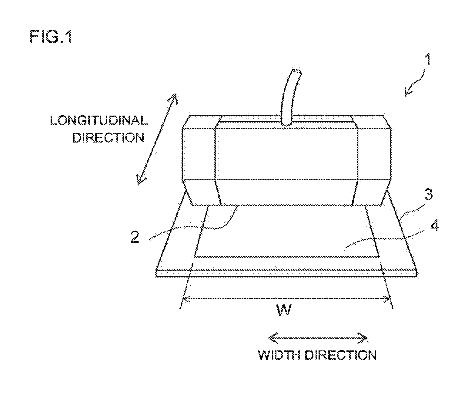
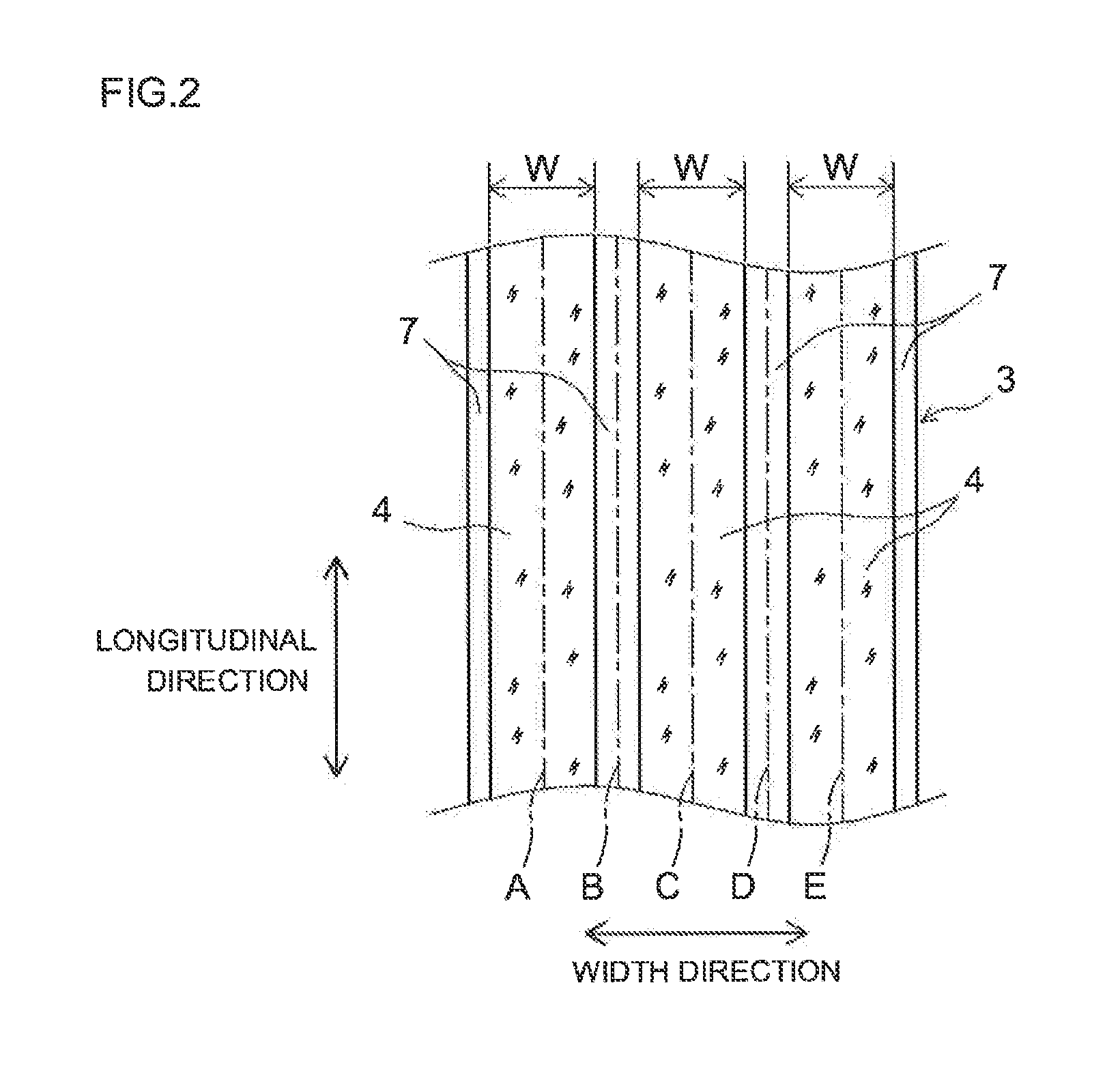
However, when producing an electrode for batteries using such a coating apparatus, a problem arose in that the width W of the coating film 4 in the transversal direction fluctuates during the operation of the apparatus, and it was not possible to form a coating film 4 of uniform coating width.

Method used


Image

  • Coating method and coating apparatus
  • Coating method and coating apparatus
  • Coating method and coating apparatus

Examples


Embodiment Construction

[0062]Preferred embodiments of the present invention are explained next with reference to accompanying drawings. Any features other than the features specifically set forth in the present description and which may be necessary for carrying out the present invention can be regarded as instances of design matter for a person skilled in the art on the basis of known techniques in the technical field in question. The present invention can be carried out thus on the basis of the features disclosed in the present description and on the basis of common technical knowledge in the relevant technical field. The embodiments below are mere illustrations of modes for carrying out the invention, and the latter is not limited in any way to the below-described embodiments.

[0063]FIG. 5 is a schematic diagram illustrating schematically a coating apparatus 100 according to the present embodiment. As illustrated in FIG. 5, the coating apparatus 100 according to the present embodiment is a coating appar...


PUM

PropertyMeasurementUnit
Viscosityaaaaaaaaaa
Sizeaaaaaaaaaa
Widthaaaaaaaaaa

Abstract

In a coating apparatus 100 provided by the present invention an electrode material paste 12 is coated onto an elongated collector 10, to form thereby a coating film 14 of predetermined width in the longitudinal direction of the collector. The coating apparatus 100 includes: a discharge nozzle 20 that discharges the paste 12 onto the collector 10, Which is an object to be coated; a transport pipe 30 that transports the paste 12 up to the discharge nozzle 20; a viscosity measurement unit 40 that measures the viscosity of the paste 12 that is transported within the transport pipe 30; and a gap control unit 50 that modifies a size H of the clearance between the discharge nozzle 20 and the collector 10 on the basis of the viscosity measured by the viscosity measurement unit 40.

Description

TECHNICAL FIELD[0001]The present invention relates to a coating method and to a coating apparatus. More particularly, the present invention relates to a coating method and a coating apparatus by which an electrode material paste is coated onto an elongated collector, to form thereby a coating film of predetermined width in the longitudinal direction of the collector.BACKGROUND ART[0002]Recent years have witnessed the growing importance of secondary batteries, for instance lithium ion batteries, as vehicle-mounted power sources, and as power sources that are provided in, for instance, personal computers and portable terminals. In particular, lithium secondary batteries that are lightweight and afford high energy density are expected to be used as preferred high-output power sources installed in vehicles. In a typical configuration, such lithium secondary batteries comprise electrodes wherein a material that is capable of reversibly storing and releasing lithium ions (electrode active...

Claims


Application Information

Patent Timeline
IPC IPC(8): H01M4/04H01M4/139
CPCH01M4/0404H01M4/0409H01M4/0411B29C47/0019B29C47/025B29C47/065B05C11/1007B29C47/92B29C2947/922B29C2947/92628B29C2947/92647B29C2947/92695B05C5/0254B29C47/32B29C48/92B29C48/07B29C48/154B29C48/21B29C48/35B29C2948/922B29C2948/92628B29C2948/92647B29C2948/92695B29C48/08Y02E60/10H01M4/04H01M4/139B05C5/02B05D7/24
Inventor SUZUKI, SHIGERU
Owner TOYOTA JIDOSHA KK
Learn More