Acquisition Memory Allocation for Digital Storage Oscilloscope

a digital storage oscilloscope and acquisition memory technology, applied in the field ofsignal acquisition instruments, can solve the problems of inability to proportion inability to share an acquisition memory, and inability to dynamically allocate memory area(s) in the acquisition memory for the selected selected devi

Inactive Publication Date: 2013-09-05
TEKTRONIX INC
View PDF1 Cites 18 Cited by
  • Summary
  • Abstract
  • Description
  • Claims
  • Application Information

AI Technical Summary

Benefits of technology

[0007]To overcome the shortcomings in the existing digital storage oscilloscope, the present invention provides improved acquisition systems.

Problems solved by technology

It is usually impossible, or at least not flexibly, to share an acquisition memory among all input channels that acquire and / or measure different analog signals under test.
Even though the existing digital storage oscilloscopes can share multiple memory areas (unusually in even number) for one input signal, they are unable to proportionally allocate memory area(s) in an acquisition memory to the selected (or active) channels that acquire and / or measure different input signals under test, but not to allocate any memory areas in the acquisition memory for the non-selected (or inactive) channels.
In other words, the existing digital storage oscilloscopes are unable to dynamically allocate memory areas in the acquisition memory for the selected (or active) channels that acquire and / or measure different input signals.
Therefore, in an existing digital storage oscilloscope, the acquisition memory resource assigned to an input channel that acquires a signal with slower speed may be unnecessarily large while the acquisition memory resource assigned to another input channel that acquires a signal with a faster speed is inadequate to re-assemble their respectively received signals.

Method used


Image

  • Acquisition Memory Allocation for Digital Storage Oscilloscope
  • Acquisition Memory Allocation for Digital Storage Oscilloscope
  • Acquisition Memory Allocation for Digital Storage Oscilloscope

Examples


Embodiment Construction

[0039]Reference is now made to the embodiments, examples of which are illustrated in the accompanying drawings.

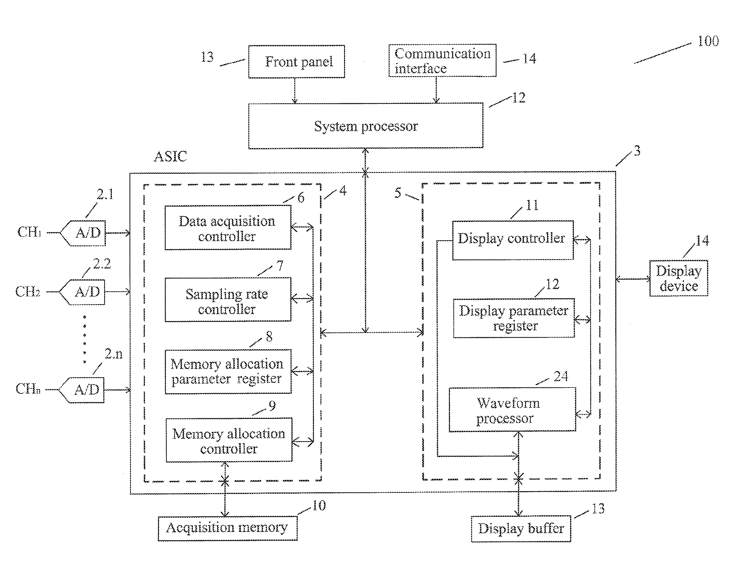
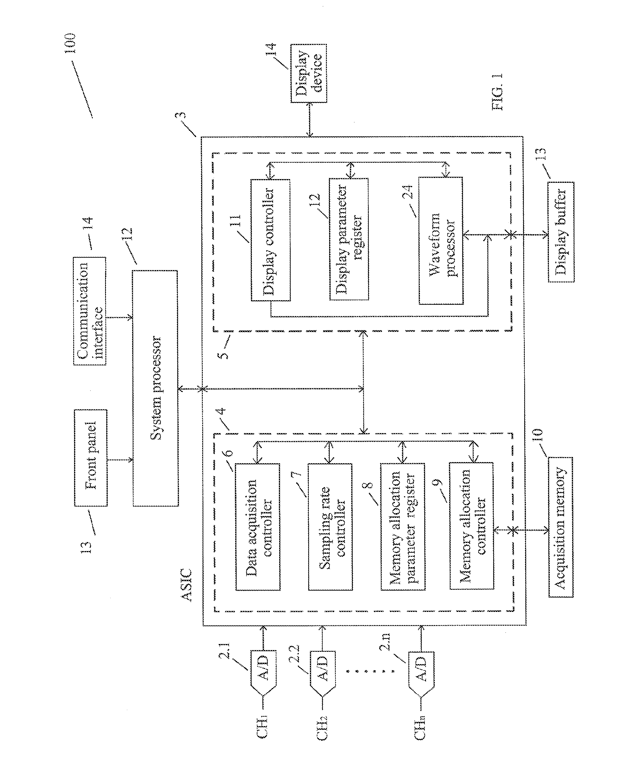
[0040]FIG. 1 shows an illustrative block diagram of a multiple channel digital storage oscilloscope 100 according to the present disclosure. As shown in FIG. 1, the digital storage oscilloscope 100 includes n channels (CH.1, CH.2, . . . , CH.n), n analog-to-digital (A / D) converters 2 (2.1, 2.2, . . . , or 2.n), a sampling date processor 3 (an Application Specific Integrated Circuit—ASIC), a system processor 12, an acquisition memory 10, a display buffer 13 and a display device 14. Each of the n channels CH.i is coupled to a corresponding convertor 2.i for receiving an analog signal under test via a probe and cable arrangement (not shown) and digitizing the received analog signal into a stream of digital samples (or sample data) at predetermined time intervals. Each of the digital samples associates with a numerical value. The digitized samples from the n A / D converters 2 (2...


PUM


Abstract

The present disclosure provides an acquisition system for oscilloscopes having n input channels. The acquisition system comprises n A/D converters (2.1, 2.2, . . . , 2.n) with each of the n A/D converters receiving a signal under test from one of n channels and digitizing the received signal into digital samples; an acquisition memory for storing the digitized samples from the n A/D converters; and a memory allocation processor for dynamically allocating memory lengths (or memory depths) for the selected n input channels within an acquisition memory based on the user setting from the oscilloscope. To efficiently use the acquisition memory, the acquisition system does not allocate any memory areas for the input channels that are not selected. In addition, the acquisition system can set up sampling rates for the n input channels based on the frequencies of the signals under test received from the n input channels.

Description

FIELD OF THE INVENTION[0001]The present disclosure relates generally to signal acquisition instruments and, more specifically, to a signal acquisition display architecture adapted for using with a digital storage oscilloscope having multiple input channels or other signal acquisition and display devices.BACKGROUND OF THE INVENTION[0002]Usually, a digital storage oscilloscope has multiple input channels with each of the multiple channels capable of receiving an analog signal under test. Each of the multiple input channels has a respective analog-to-digital (A / D) converter to digitize the received analog signal under test into a stream of digital samples (or sample data) at a predetermined sampling rate. As known in the field, a digital storage oscilloscope includes an acquisition memory to store multiple streams of digitized samples to represent the analog signals under test. After accumulating enough digital samples in the acquisition memory, the digital storage oscilloscope re-asse...

Claims


Application Information

Patent Timeline
Patent Type & Authority Applications(United States)
IPC IPC(8): G01R13/02
CPCG01R13/0236G01R13/0272G01R13/029
Inventor YU, HAIWEN
Owner TEKTRONIX INC
Why Eureka
Try Eureka