Eureka AIR delivers breakthrough ideas for toughest innovation challenges, trusted by R&D personnel around the world.

Optical instrument and method for obtaining distance and image information

a technology of optical instruments and distance and image information, applied in instruments, measurement devices, surveying and navigation, etc., can solve the problems of difficult obtaining the coordinates of the exact position to be measured, time-consuming, and time-consuming for three-dimensional data acquisition, so as to improve image acquisition accuracy and speed, improve data acquisition, and improve the effect of distance measurement accuracy

Active Publication Date: 2010-02-04
TRIMBLE JENA
View PDF7 Cites 48 Cited by
  • Summary
  • Abstract
  • Description
  • Claims
  • Application Information

AI Technical Summary

Benefits of technology

[0009]It is therefore desirable to provide an optical instrument and method with improved data acquisition for improving image acquisition and the accuracy and speed of distance measurements.
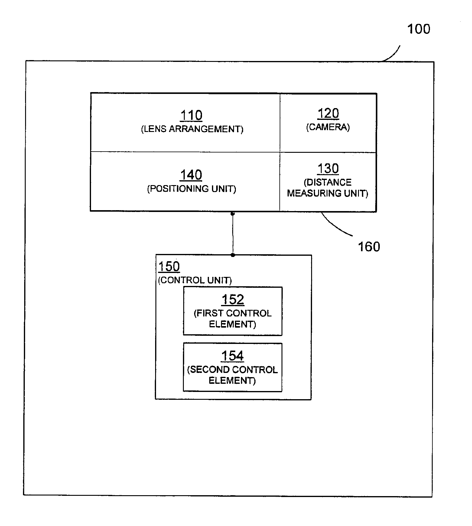
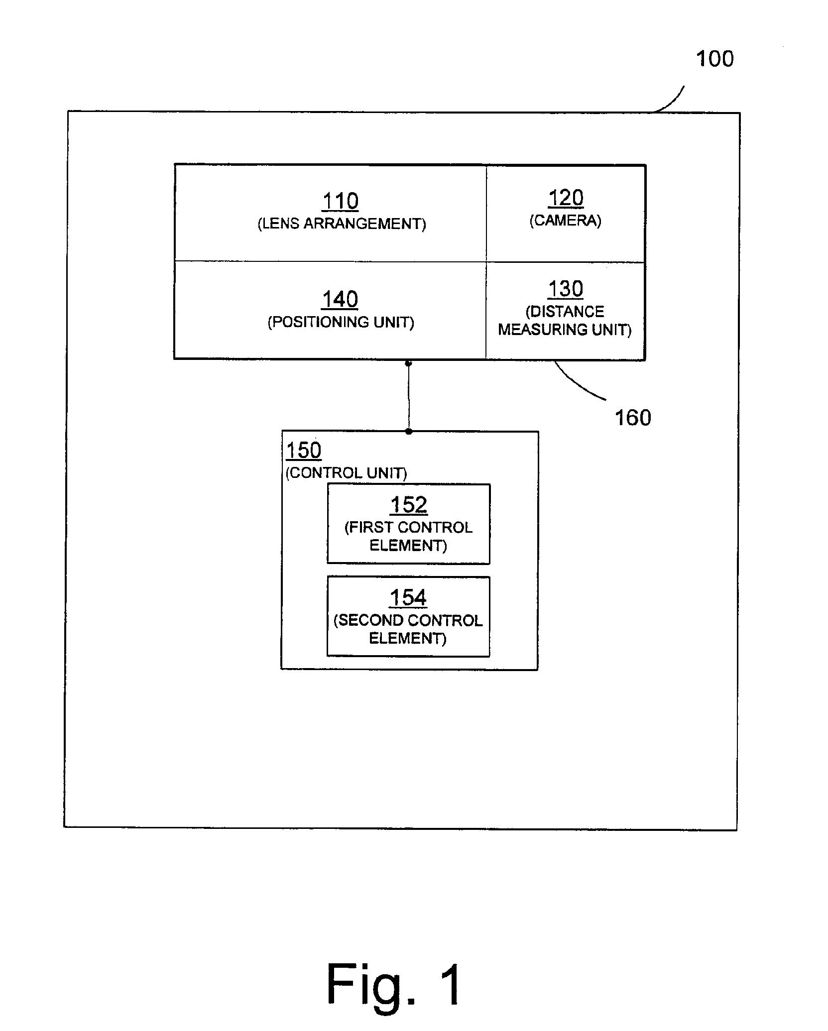
[0010]According to an embodiment, an optical instrument for obtaining distance and image information of an object, comprises a lens arrangement for sighting the object, a camera aligned with the optical axis of the lens arrangement for acquiring an image of at least part of the object, a distance measuring unit for measuring a distance to the object along a measurement axis of the distance measuring unit parallel to the optical axis of the lens arrangement, a positioning unit for adjusting the optical axis of the lens arrangement relative to at least one reference axis, and a control unit having a first control element adapted to define in the image an area to be scanned, to obtain a plurality of measurement pixels of the object within the area and to convert the plurality of measurement pixels into an approximation of coordinates of a plurality of positions to be measured assuming a default distance between the plurality of positions and the optical instrument, and a second control element adapted to instruct the positioning unit to adjust the optical axis of the lens arrangement onto the plurality of positions to be measured and to instruct the distance measuring unit to measure the distances to the plurality of positions, wherein the first control element is further adapted to recalculate the coordinates of the plurality of positions based on the measured distances. Accordingly, the horizontal and vertical directions and distances of a plurality of positions on the object may be precisely measured, since the positioning unit is used to adjust the optical axis of the lens arrangement anew for each measurement, and the exact coordinates of the positions are recalculated based on the measured distances constituting an iterative process.

Problems solved by technology

However, after acquiring an image with such an optical instrument, the acquisition of three-dimensional data is time consuming.
For example, for measuring a three-dimensional grid, the instrument has to sequentially scan by tilting and panning the distance measuring means and measure each position corresponding to a point in the grid, which is time consuming.
However, the correspondence between a pixel taken by the camera and a position to be measured may not be linear so that obtaining the coordinates of the exact position to be measured is difficult and thus distance measurements may vary.
Of course, the higher the requirements on the resolution, the more data points need to be obtained, leading to a vast amount of information that has to be processed, which is often only possible offline.
Moreover, in the mirror scanning systems, it is not possible to obtain a second distance measurement of the exact same position, since it is not possible to obtain the exact same laser beam deflections on, for example, the rotating polygon mirror twice.
Further, since processing of the large amount of data has to be done usually offline back in the office, the operator cannot return to features of interest on site.
Thus, although fairly high resolution is obtained for the whole scanning area, this turns into a disadvantage if data corresponding to a few features of interest in the scanned area have to be isolated.

Method used


Image

  • Optical instrument and method for obtaining distance and image information
  • Optical instrument and method for obtaining distance and image information
  • Optical instrument and method for obtaining distance and image information

Examples


Embodiment Construction

[0047]Preferred embodiments of the invention are described with reference to the Figures. It is noted that the following description contains examples only and should not be construed as limiting the invention.

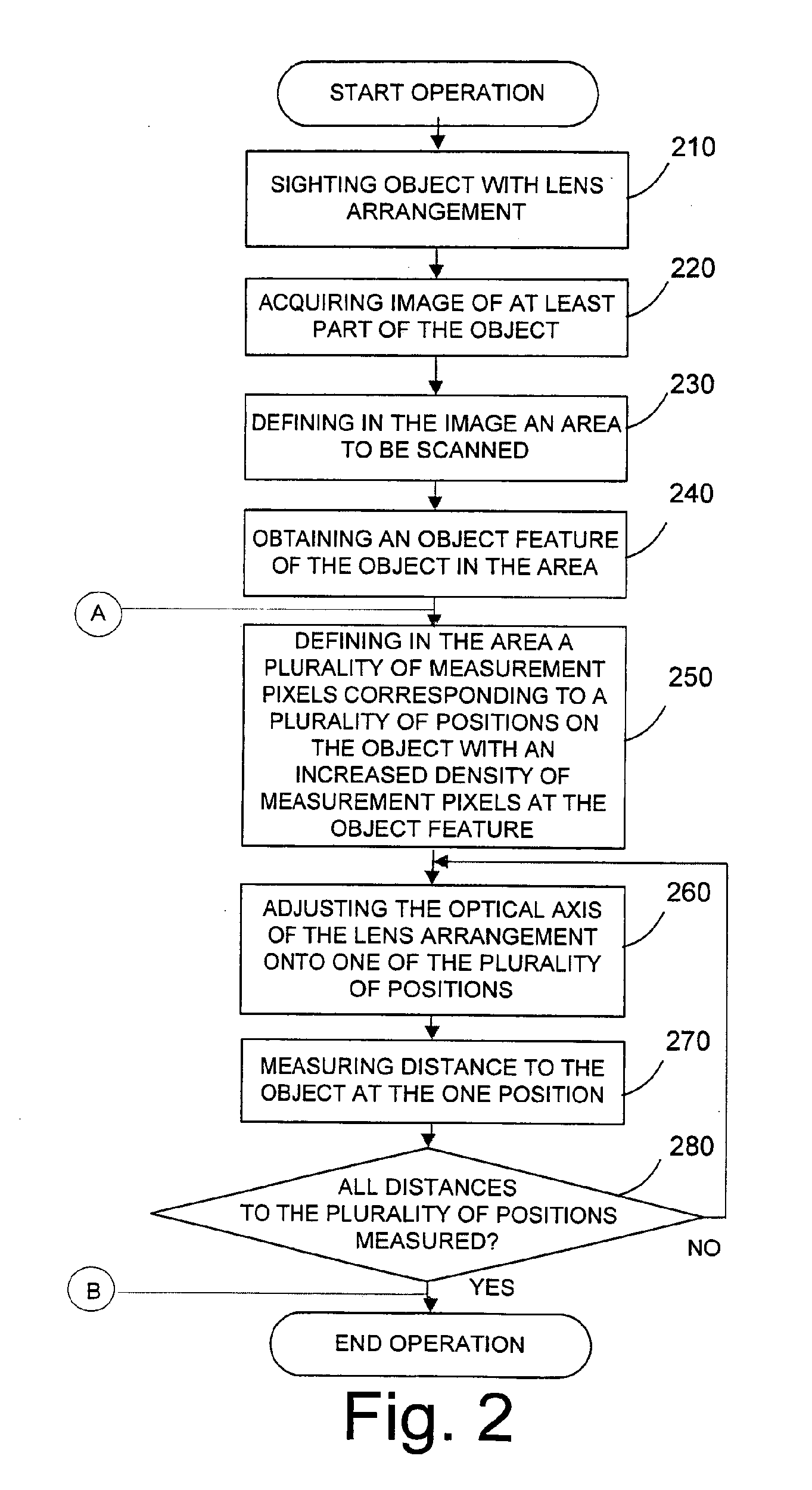
[0048]Embodiments of the invention generally relate to obtaining distance and image information of an object, and particularly, to improve the speed of data acquisition by intelligently selecting positions to be measured and to improve the accuracy of data acquisition by recalculating coordinates of selected positions on an object. Briefly said, an image is acquired with a camera and an area to be scanned and measurement pixels of an object are defined in the image, wherein the measurement pixels are converted into an approximation of coordinates of positions to be measured assuming a default distance to the positions, and the optical axis of a lens arrangement is adjusted sequentially onto the positions to be measured and after measuring the distances to the positions, the co...


PUM


Abstract

An optical instrument and a method for obtaining distance and image information of an object is disclosed to improve the speed and accuracy of data acquisition. The instrument comprises a camera, positioning unit, distance measuring unit, lens arrangement and control unit. The camera acquires images of an object and the control unit defines an area to be scanned and measurement pixels of an object in the image, wherein the measurement pixels are converted into an approximation of coordinates of positions to be measured assuming a default distance to the positions, and the optical axis of the lens arrangement is adjusted sequentially onto the positions to be measured. After measuring the distances to the positions, the coordinates are recalculated increasing the accuracy of the coordinates.

Description

CROSS-REFERENCES TO RELATED APPLICATIONS[0001]This application claims priority to International Patent Application No. PCT / EP2007 / 000706, filed on Jan. 26, 2007, the disclosure of which is hereby incorporated by reference in its entirety for all purposes.BACKGROUND OF THE INVENTION[0002]The present invention relates to an optical instrument and a method for obtaining distance and image information of an object.[0003]Optical Instruments, and in particular optical instruments, such as video tachymeters or video total stations, comprise a complex arrangement of optical elements such as lenses of a telescope, a camera and distance measuring means for obtaining information regarding the shape and the location of an object. This information may include horizontal and vertical angles and a distance to the object as well as an image of the object. The information may then be used to create a three-dimensional representation of the object.[0004]However, after acquiring an image with such an ...

Claims


Application Information

Patent Timeline
IPC IPC(8): G01C3/08
CPCG01C15/00G01C11/025
Inventor KLUDAS, TORSTENVOGEL, MICHAELGRASSER, CHRISTIANSVANHOLM, SET
Owner TRIMBLE JENA
Why Eureka
Eureka Blog
Learn More