
Assembly of prefabricated elements to form a prefabricated building with at least two floors and related building and installation process

Inactive Publication Date: 2013-09-12
DB2
View PDF8 Cites 19 Cited by
  • Summary
  • Abstract
  • Description
  • Claims
  • Application Information

AI Technical Summary

Benefits of technology

The patent text describes a configuration for the floors of a building that allows for faster installation. The design includes a lateral end wall that helps support the roof floor and is connected to the floor or roof floor through a gasket or low-depth element. The end wall can rotate, which simplifies the installation process. The configuration also allows for the use of the vertical position of the end wall to support loads and allows for easy movement. Overall, the design provides adequate structural strength and simplifies the assembly process of the building.

Problems solved by technology

In particular, U.S. Pat. No. 3,857,211 shows a multilevel prefabricated building wherein the walls and the floors are hinged to one another according to horizontal axes, obtaining somewhat complicated configurations both of hinge mechanisms and in terms of space, said complexity reflecting on the external dimensions of the compacted building prior to installation, external dimensions which are undoubtedly excessively large with respect to requirements both of transportation and of final habitable area of the building.

Method used


Image

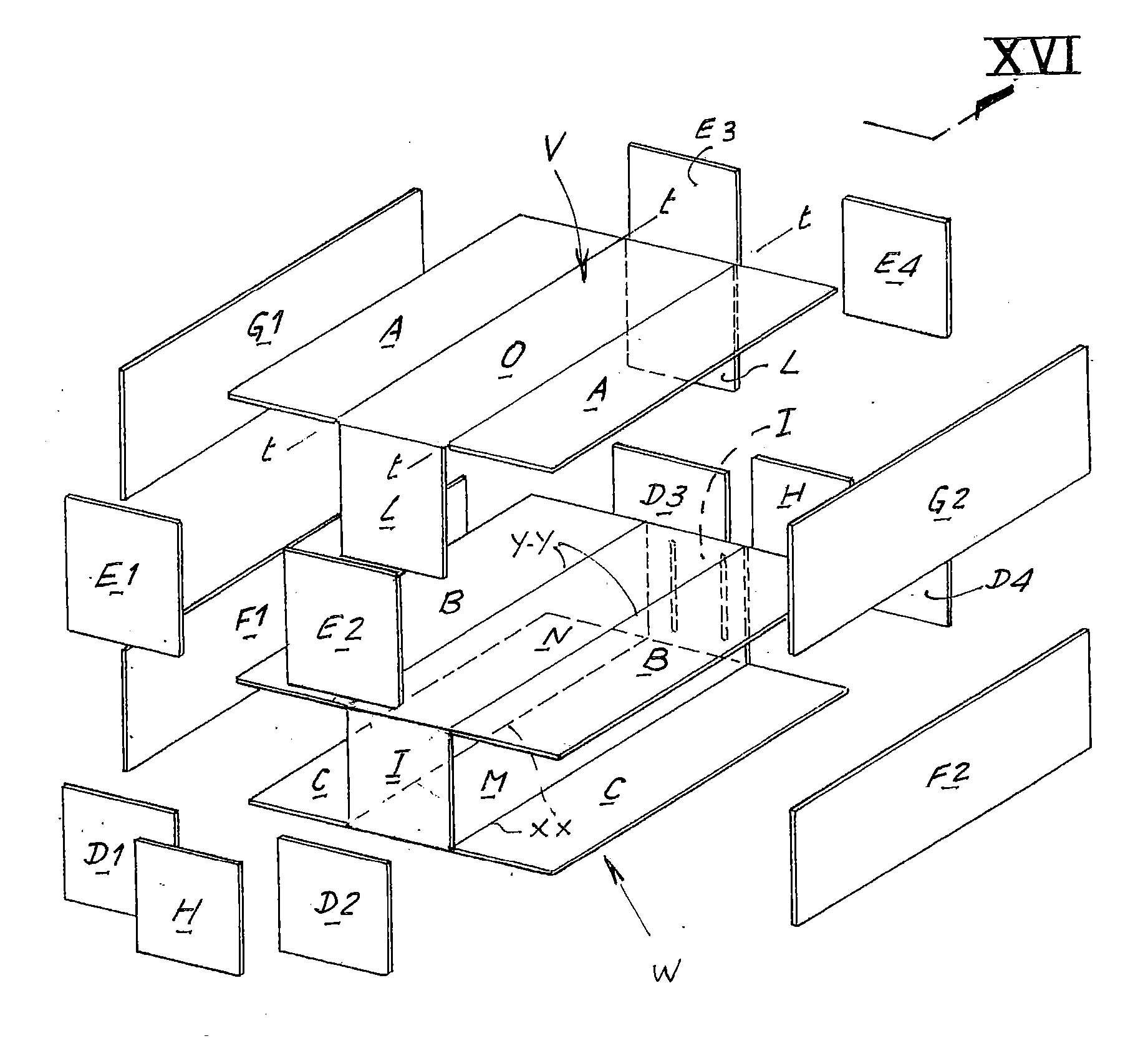
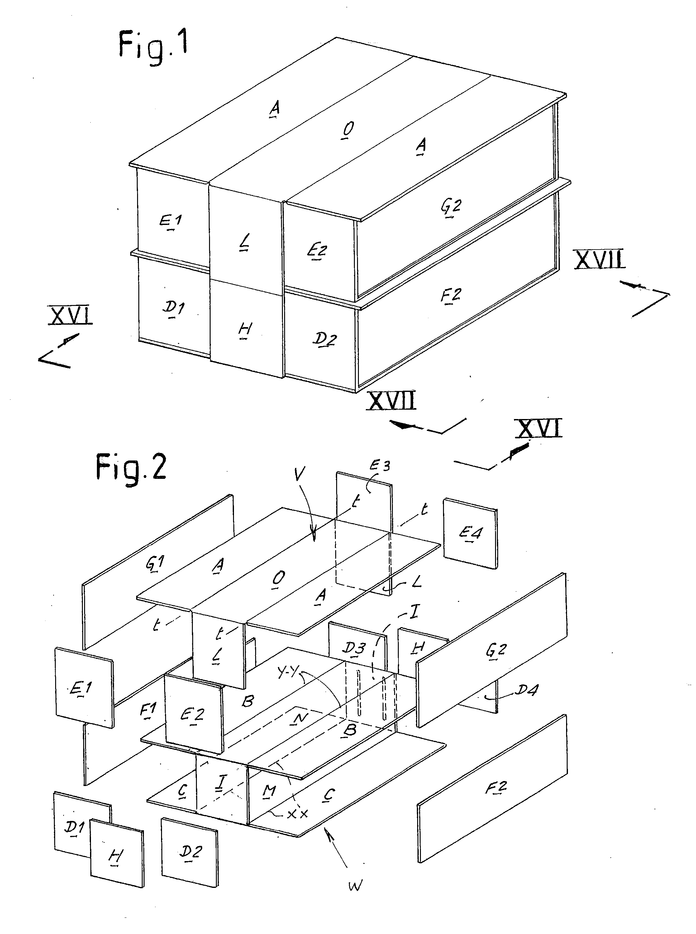
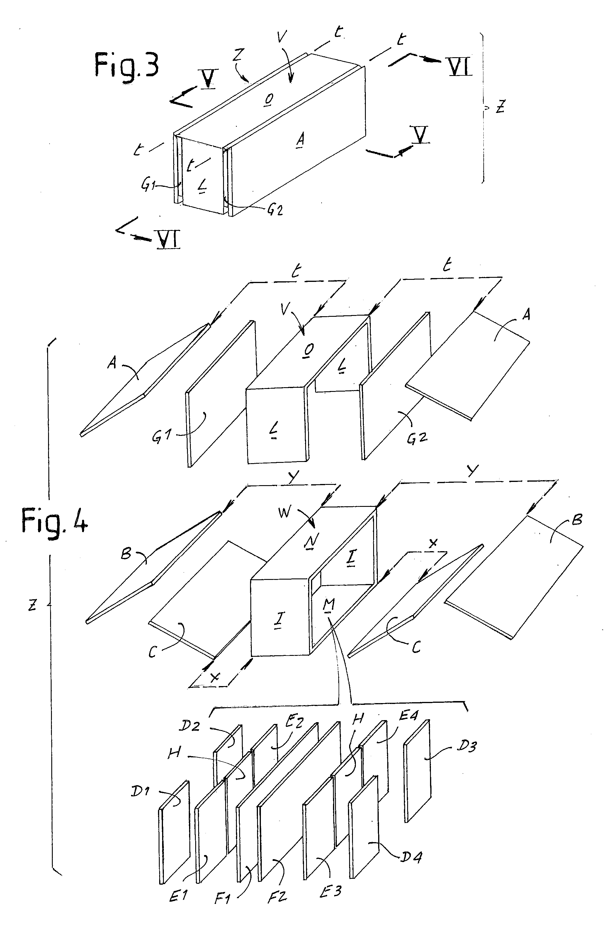
  • Assembly of prefabricated elements to form a prefabricated building with at least two floors and related building and installation process
  • Assembly of prefabricated elements to form a prefabricated building with at least two floors and related building and installation process
  • Assembly of prefabricated elements to form a prefabricated building with at least two floors and related building and installation process

Examples


third embodiment

[0228]FIGS. 43, 44 and 53 show a The letters identifying the components of the grouping assembly are the same as the examples described above, varying only the arrangement of these components in the grouping Z and the mode of carrying out assembly.

[0229]In this embodiment, the structural casing of the assembly and therefore of the building is formed by a “reticular” or “punctiform” structure (FIG. 53). In practice the frame of the primary structure is formed by sections or beams made of metal (or another material, such as wood) which form the nine flat parts or frames with rectangular shape (the portions of floor M, C, N, B, O, A) which, after reaching the final position, form the walk floors of the ground story M-C, of the intermediate or second story N-B and the roof floors O-A. The secondary framework of the flat frames is for example composed of cold press-formed C sections.

[0230]For vertical support, the structural casing is provided with columns MG1 fixed permanently at the e...

fourth embodiment

[0253]FIGS. 66 and 67 show a The letters identifying the components of the grouping assembly are the same as the examples described above, varying only the arrangement of these components in the grouping Z and the mode of carrying out assembly.

[0254]In grouping configuration Z, the assembly consists of the following longitudinal arrangement of components (starting from the longitudinal vertical centerline plane of the grouping, outward; as the grouping is symmetrical, only the components referring to one side of the grouping will be indicated, indicating only the reference letter and not the number, which indicates the corresponding side):[0255]a pair of first transverse lateral end walls D-D relating to the first lateral portions of floor C,[0256]the first longitudinal wall F of the ground story,[0257]a pair of second transverse lateral end walls E-E relating to the second lateral portions of floor B,[0258]the first lateral portion C of the walk floor of the ground story,[0259]the...

fifth embodiment

[0263]FIGS. 68 and 69 show a The letters identifying the components of the grouping assembly are the same as the examples described above, varying only the arrangement of these components in the grouping Z and the mode of carrying out assembly.

[0264]In grouping configuration Z, the assembly consists of the following longitudinal arrangement of components (starting from the longitudinal vertical centerline plane of the grouping, outward; as the grouping is symmetrical, only the components referring to one side of the grouping will be indicated, indicating only the reference letter and not the number, which indicates the corresponding side):[0265]a pair of first transverse lateral end walls D-D relating to the first lateral portions of floor C,[0266]the first longitudinal wall F of the ground story,[0267]a pair of second transverse lateral end walls E-E relating to the second lateral portions of floor B,[0268]the second longitudinal wall G of the second story,[0269]the first lateral ...


PUM


Abstract

The assembly of prefabricated elements to form a prefabricated building with two stories includes:a prefabricated hollow structure (W) formed by portions of the walk floors of the ground floor and of the floor above (M, N) permanently connected to one another by portions of transverse walls (I) of the ground floor, anda prefabricated portal structure (V) formed by a central portion (O) of the roof floor of the upper story connected permanently to two portions of transverse walls (L) of the same story, the portal structure (V) being designed to be fixed on top of the structure (W).

Description

CROSS REFERENCE TO RELATED APPLICATIONS[0001]This application is a United States National Phase application of International Application PCT / IB2011 / 000958 and claims the benefit of priority under 35 U.S.C. §119 of Italian Patent Application FI2010A000096 filed May 7, 2010, the entire contents of which are incorporated herein by reference.FIELD OF THE INVENTION[0002]The present invention relates to the field of prefabricated buildings, in particular for residential use.BACKGROUND OF THE INVENTION[0003]There are known prefabricated buildings with only one wherein the walls, walk floor and roof floor can be separate into elements of small dimension designed to be placed adjacent to one another to form an easily transportable compact assembly, elements which if necessary can be joined to one another by means of hinges to facilitate assembly on site thereof. In general, these are temporary buildings to be erected rapidly for emergencies, such as military quartering or the like, for examp...

Claims


Application Information

Patent Timeline
IPC IPC(8): E04B1/343E04H1/00
CPCE04B1/3442E04H1/005E04B1/34315
Inventor DONNINI, MANUELE
Owner DB2
Learn More