Hot processing clamp

A fixture and component technology, applied in the field of heat treatment fixtures, can solve problems such as difficulty in ensuring mechanical strength and easy deformation

Active Publication Date: 2015-03-18
MURATA MFG CO LTD +1
View PDF6 Cites 3 Cited by
  • Summary
  • Abstract
  • Description
  • Claims
  • Application Information

AI Technical Summary

Problems solved by technology

However, since there are many through holes, it is difficult to ensure mechanical strength and is easy to deform if it is not reinforced by fringing the surrounding edges with a metal plate as in the Japanese Unexamined Publication No. 63-095095. It can be transported without snaking on the rollers in the heat treatment furnace

Method used


Image

  • Hot processing clamp
  • Hot processing clamp
  • Hot processing clamp

Examples


Embodiment approach 1

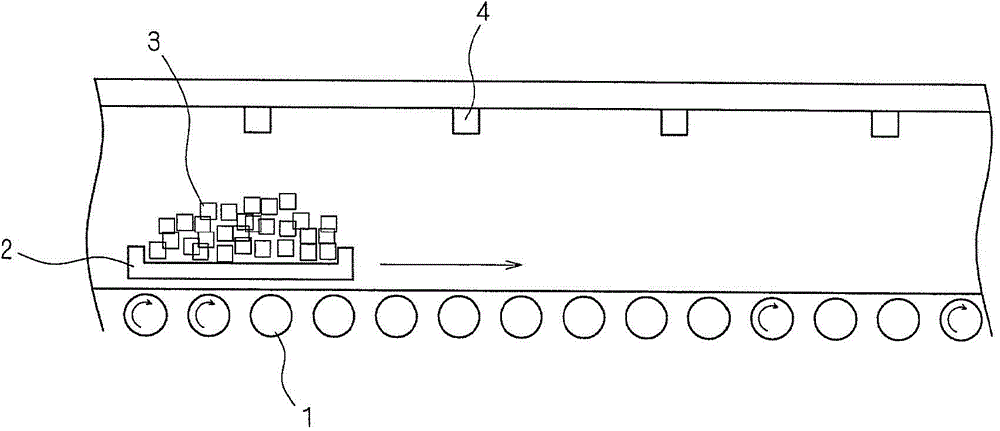
[0037] figure 1 It is a schematic diagram showing the structure of a heating device using a conventional heat treatment jig. figure 1 Shown in the so-called rolling heating device. Such as figure 1 As shown, a plurality of rotatable rollers 1 are provided on the bottom surface of the furnace (heat treatment furnace) of the heating device, and chip-shaped (ceramic) electronics are randomly placed on the loading surface of the heat treatment jig 2. Components 3, such as laminated bodies such as chip-shaped ceramic capacitors and chip-shaped inductors, and the above-mentioned electronic components 3 are passed through the heating furnace along the direction of the arrow in the figure. The heated shielding gas is sprayed from the gas injection port 4 in the upper part of the heating furnace, and the passing chip-like electronic component 3 is heat-treated. It goes without saying that the gas injection port 4 is not necessarily provided at the upper part of the heating furnace, ...

Embodiment approach 2

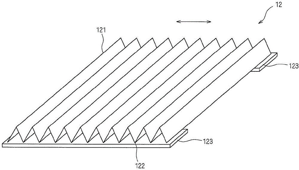
[0053] The heat treatment jig 12 of Embodiment 2 is the same as Embodiment 1 in that it has a loading surface provided with a plurality of through holes (first through holes), and the loading surface is composed of accordion-shaped concavities and convexities that are alternately and repeatedly folded into peaks and valleys. face composition. What is different from Embodiment 1 is that instead of reinforcing plate 123, the bottom and side portions of both ends in the direction perpendicular to the direction (folding direction) in which peaks and valleys are alternately and repeatedly formed are provided with L-shaped cross-sections. Enhanced parts.

[0054] Figure 5 It is a perspective view showing the structure of the heat treatment jig 12 according to Embodiment 2 of the present invention. Such as Figure 5 As shown, the loading surface of the jig 12 for heat treatment is formed by alternately and repeatedly folding a metal plate having a plurality of through holes, such...

Embodiment approach 3

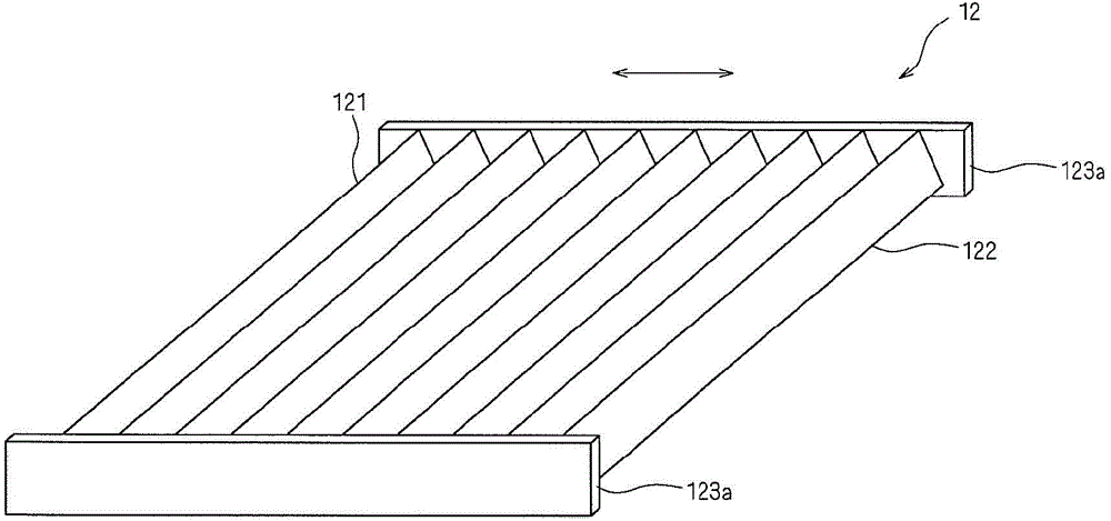
[0072] The jig 12 for heat treatment according to Embodiment 3 of the present invention will be described below. The heat treatment jig 12 of the present embodiment is the same as Embodiment 1 in that it has a loading surface provided with a plurality of through holes (first through holes), and the loading surface is composed of a concertina-shaped concave-convex surface that is alternately and repeatedly folded into peaks and valleys. to form. In addition, the reinforcing plate 123a is provided as the first reinforcing member, which is combined with that in Embodiment 1. image 3 The structure described is the same. However, this embodiment Figure 8 and Figure 9 As shown, the heat treatment jig 12 includes a guide member 131 . Figure 8 is a stereogram, Figure 9 is a side view.

[0073] In the heat treatment jig 12 of this embodiment, a guide member 131 for connecting the pair of first reinforcement members to each other is provided between the reinforcement plates 1...


PUM


Abstract

A hot processing clamp (12) is used for hot processing chip electronic parts, and comprises a carrier part; the carrier part is repeatedly folded into peaks and valleys, thus forming a waveform used for carrying the electronic parts; the carrier part has a plurality of through holes bigger than the electronic parts; the clamp also comprises a pair of reinforcement plates (123) for a first reinforcement part; a waveform forward direction is a first direction, a horizontal direction orthogonal to the first direction is a second direction, the reinforcement plate (123) is not arranged on two ends of the first direction of the carrier part, but arranged on a bottom or side portion of two ends of the second direction of the carrier part.

Description

technical field [0001] The present invention relates to a jig for heat treatment used for heat treatment of chip-shaped ceramic electronic components. Background technique [0002] In the process of manufacturing chip-shaped ceramic electronic parts, heat treatments such as debonding treatment and firing treatment of ceramic moldings are performed using heating devices such as continuous heat treatment furnaces and batch heat treatment furnaces. For example, when performing firing treatment (heat treatment) of the ceramic molded body, the ceramic molded body is passed through a heating furnace (heat treatment furnace) in a state accommodated in a jig for heat treatment. [0003] The jig for heat treatment has a mounting surface on which a ceramic molded body is mounted, and is generally formed of a flat-plate mesh. The jig for heat treatment is loaded on the ceramic plate, and is transported into the heat treatment furnace by rollers installed at the lower part of the heati...

Claims


Application Information

Patent Timeline
IPC IPC(8): F27D5/00
Inventor 秋本茂森井博史近藤信之
Owner MURATA MFG CO LTD
Why Eureka
Try Eureka