Supercharge Your Innovation With Domain-Expert AI Agents!

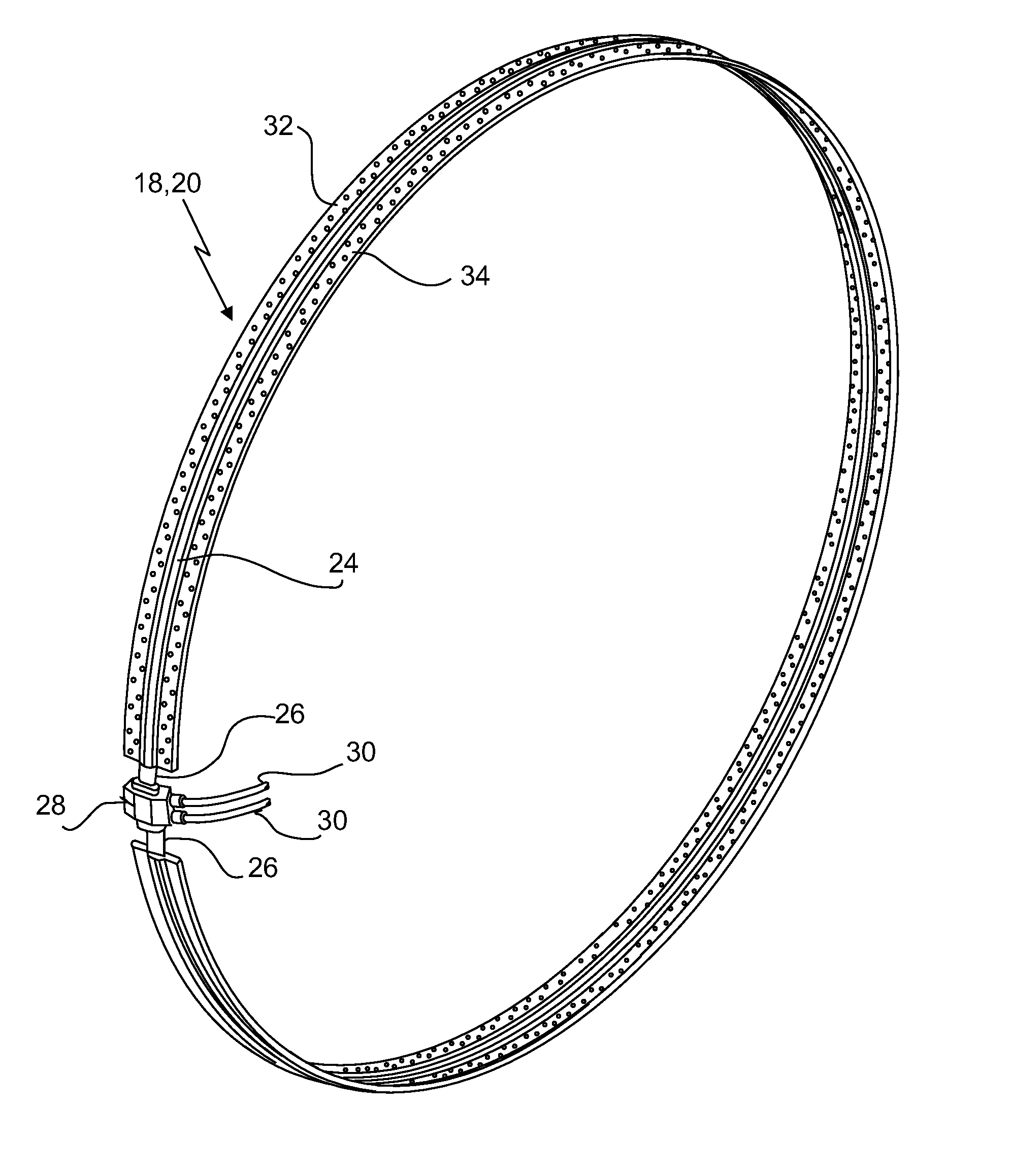
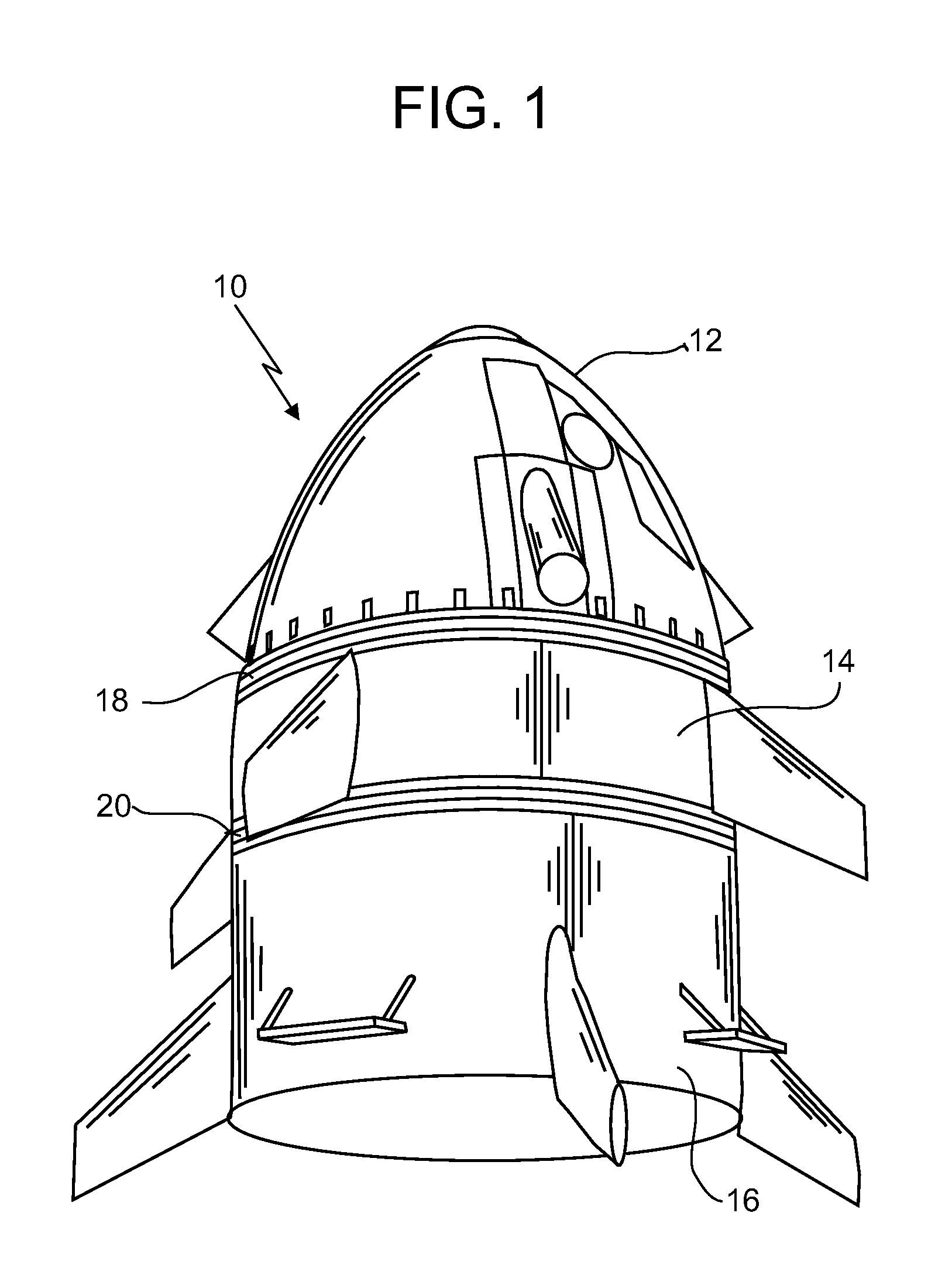
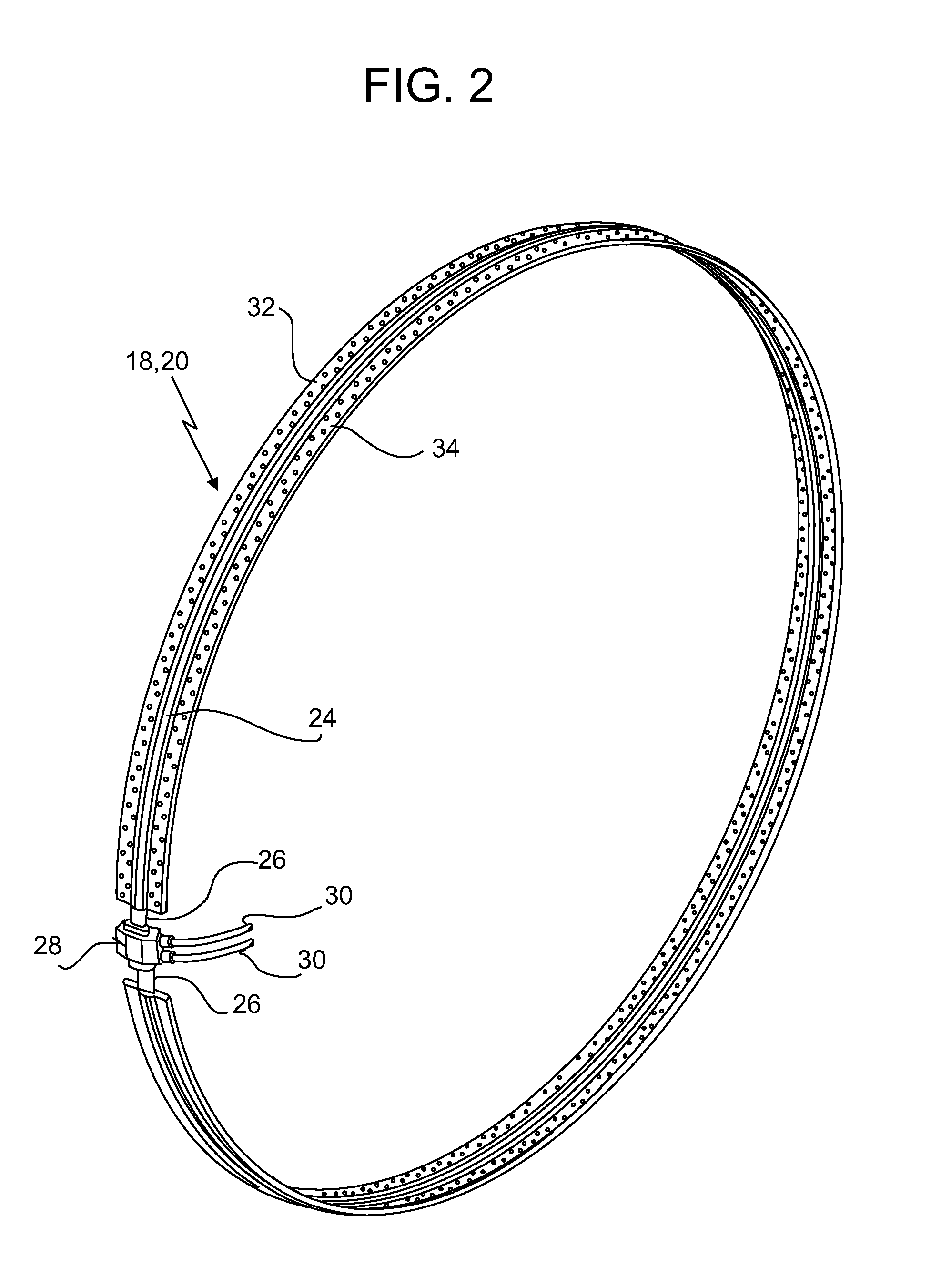
Overextrusion of silicone rubber charge holder on metal wire rope

a technology of metal wire rope and silicone rubber, which is applied in the field of frangible separation joints, can solve the problems of less than desired mechanical retention amount of silicone rubber charge holder within metal confinement tubes, silicone rubber charge holder tends to move and/or deform during vehicle flight, and achieves the effect of improving the retention of elastomeric charge holder in pla

Active Publication Date: 2013-09-12
ENSIGN BICKFORD AEROSPACE & DEFENSE
View PDF3 Cites 7 Cited by
  • Summary
  • Abstract
  • Description
  • Claims
  • Application Information

AI Technical Summary

Benefits of technology

The invention relates to an elastomeric charge holder which has one or more holes where an explosive charge can be placed. The holder also has metal wires embedded within it. The holder may be over-molded or over-extruded over the metal wires to keep them in place during use. The metal wires help to make a better match of thermal coefficients with the metal confinement tube that holds the holder, which improves the retention of the holder in place during initiation of the explosive charge.

Problems solved by technology

Problems with such a frangible separation joint include the fact that the silicone rubber charge holder tends to thermally contract and / or undergo acceleration compression or deformation during the various stages of flight of the flight vehicle structure.
As a result, a less than desired amount of mechanical retention of the silicone rubber charge holder within the metal confinement tube occurs.
That is, the silicone rubber charge holder tends to move and / or deform during vehicle flight.
Also, a relatively large mismatch of the coefficients of thermal expansion occurs between the silicone rubber charge holder and the surrounding aluminum or stainless steel confinement tube.
This causes a lack of control of the expansion and contraction between the silicone charge holder and the surrounding metal confinement tube during the various stages of flight of the flight vehicle structure.

Method used


Image

  • Overextrusion of silicone rubber charge holder on metal wire rope
  • Overextrusion of silicone rubber charge holder on metal wire rope
  • Overextrusion of silicone rubber charge holder on metal wire rope

Examples


Embodiment Construction

[0019]The present invention is more particularly described in the following description and examples that are intended to be illustrative only since numerous modifications and variations therein will be apparent to those skilled in the art. As used in the specification and in the claims, the singular form “a,”“an,” and “the” may include plural referents unless the context clearly dictates otherwise. Also, as used in the specification and in the claims, the term “comprising” may include the embodiments “consisting of” and “consisting essentially of.” Furthermore, all ranges disclosed herein are inclusive of the endpoints and are independently combinable.

[0020]As used herein, approximating language may be applied to modify any quantitative representation that may vary without resulting in a change in the basic function to which it is related. Accordingly, a value modified by a term or terms, such as “about” and “substantially,” may not to be limited to the precise value specified, in ...


PUM


Abstract

An elastomeric charge holder includes one or more holes formed therein into which is disposed an explosive charge. The elastomeric charge holder further includes one or more metal wires also disposed within the elastomeric charge holder. The elastomeric charge holder may be over molded or over extruded over each of the one or more metal wires, thereby retaining each of the one or more wires in place during use of the elastomeric charge holder. The one or more wires are also a better match of thermal coefficients to a metal confinement tube that holds the elastomeric charge holder, which results in improved retention of the elastomeric charge holder in place, particularly during initiation of the explosive charge.

Description

FIELD OF THE INVENTION[0001]The present invention relates in general to frangible separation joints utilized in flight vehicle structures, and in particular, to such a frangible separation joint having an expansion device located there within that contains an explosive charge (e.g. a mild detonating fuse) disposed within an elastomeric (e.g., silicone rubber) charge holder along with one or more metal wires also disposed within the charge holder, where the elastomeric charge holder is over molded or over extruded onto the metal wires for improved retention of the charge holder in its desired location through all of the various operating stages of the flight vehicle structure.BACKGROUND OF THE INVENTION[0002]Various types of flight vehicle structures such as rockets, missiles, satellites, and the like are typically configured in a plurality of stages. When in use, these vehicle flight structures oftentimes need to separate one stage from another on command at a specific time during v...

Claims


Application Information

Patent Timeline
Patent Type & Authority Applications(United States)
IPC IPC(8): F42B15/38
CPCF42B15/38
Inventor KAMETZ, DAVIDDUPREY, KEVIN
Owner ENSIGN BICKFORD AEROSPACE & DEFENSE
Features
  • R&D
  • Intellectual Property
  • Life Sciences
  • Materials
  • Tech Scout
  • Unparalleled Data Quality
  • Higher Quality Content
  • 60% Fewer Hallucinations
Learn More