Heat conducting device and electronic device applying the same

Inactive Publication Date: 2013-09-12
HUAWEI TECH CO LTD
View PDF7 Cites 14 Cited by
  • Summary
  • Abstract
  • Description
  • Claims
  • Application Information

AI Technical Summary

Benefits of technology

[0009]The heat conducting device and the electronic device applying the heat conducting device provided in embodiments of this invention may adjust its own thickness through sliding between an upper heat conducting arm and a lower heat conducting arm accordi

Problems solved by technology

In current electronic devices, with the continuous abundant of functions, corresponding power consumption is constantly increasing, as a result, heat dispersion of electronic devices has become an important issue restricting the development of electronic devices.
Due to manufacture errors, the distance between the heat source of an electronic product and an heat dispersion devi

Method used


Image

  • Heat conducting device and electronic device applying the same
  • Heat conducting device and electronic device applying the same
  • Heat conducting device and electronic device applying the same

Examples


first embodiment

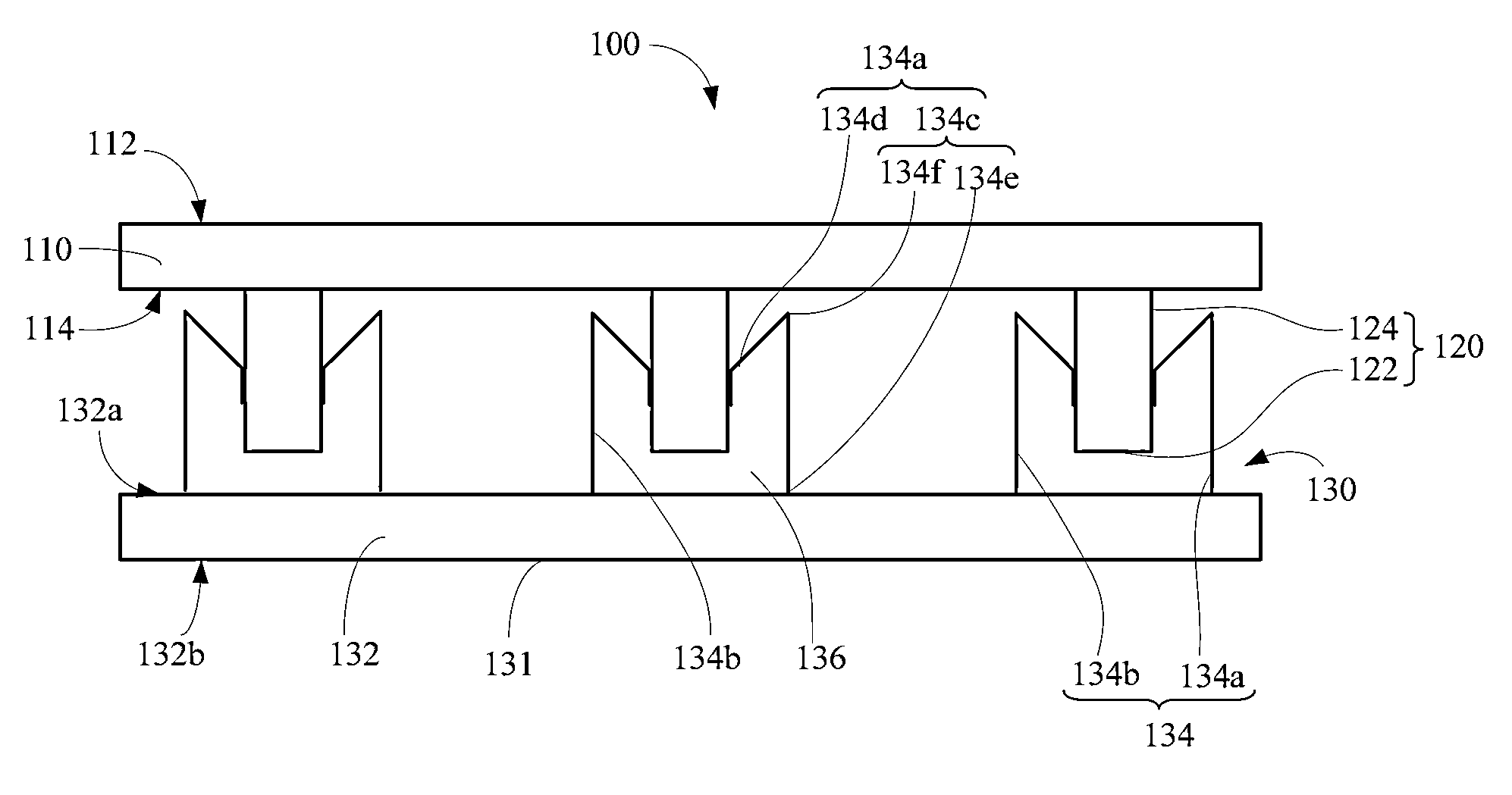
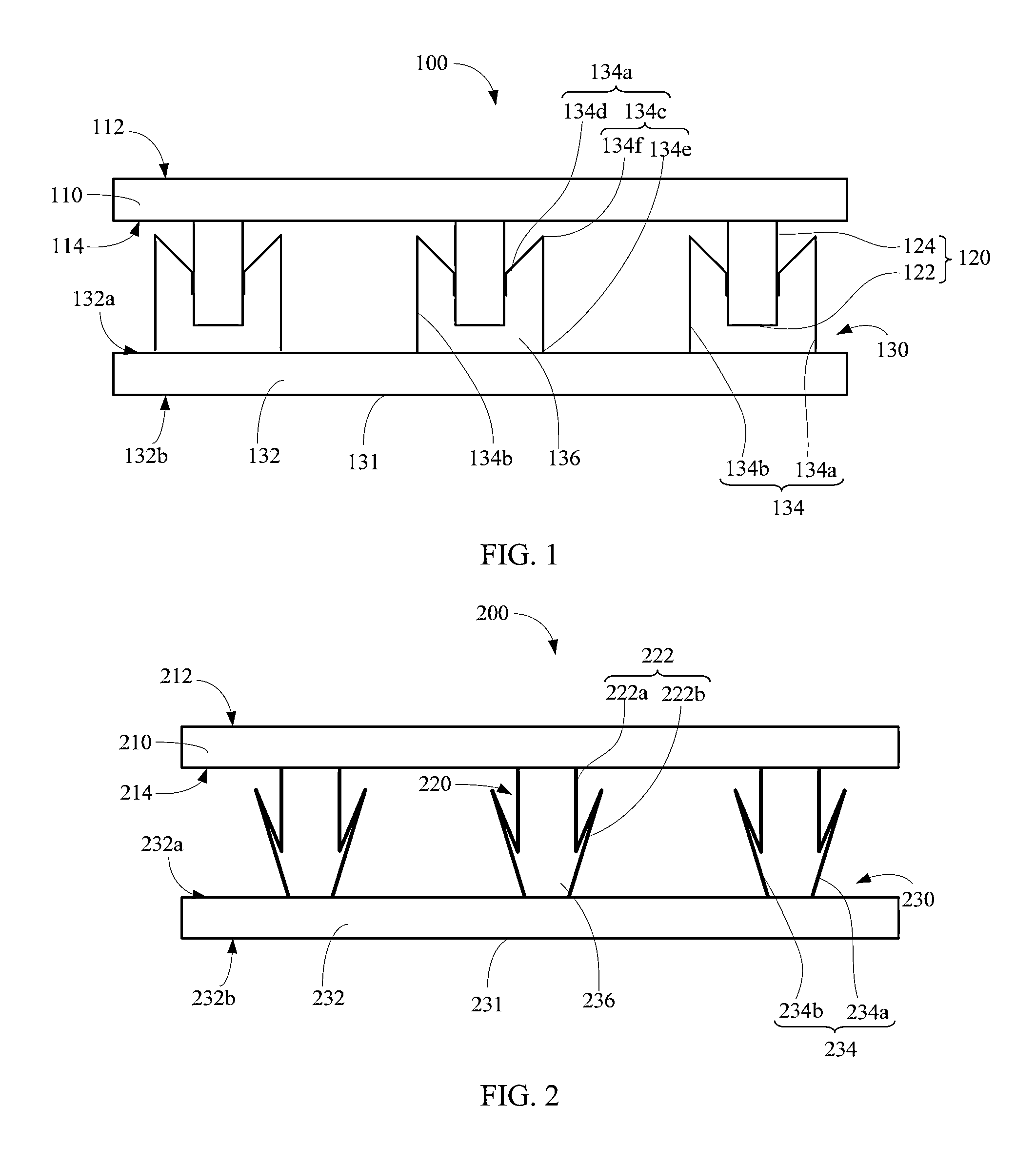
[0027]Referring to FIG. 1, FIG. 1 is a side view of a heat conducting device 100 provided in this invention. The heat conducting device 100 comprises a first heat conducting board 110 and a heat conducting structure 130. The first heat conducting board 110 comprises at least one upper heat conducting arm 120 provided on a side surface of the first heat conducting board 110. The heat conducting structure 130 slidably abuts on the upper heat conducting arm 120 of the first heat conducting board 110 to form a contact surface through which heat transfer is performed. The heat conducting structure 130 comprises a heat conducting surface 131 contacting with a heat source or a heat dispersion device, the heat conducting structure 130 is used to keep a relative position of the first heat conducting board 110 and the heat conducting surface 131, and the distance between the first heat conducting board 110 and the heat conducting surface 131 of the heat conducting structure 130 may be varied ...

third embodiment

[0043]In use, each upper heat conducting arm 420 on the first heat conducting board 410 corresponds to adjacent resilient boom segments 434c of two adjacent boom-type lower heat conducting arms 434 of the heat conducting structure 430, and the end surface 422 of the upper heat conducting arm 420 is abutted against the resilient boom segments 434c. Then, a prepressure is applied on the first heat conducting board 410 to insert the upper heat conducting arm 420 between the two adjacent boom-type lower heat conducting arms 434. The resilient boom segments 434c of the adjacent boom-type lower heat conducting arm 434 produce a resilient deformation toward the locating segment 434a under the prepressure. At that point, a taper side 426 formed on the upper heat conducting arm 420 is closely abutted against the folded resilient boom segments 434c to cause sufficiently contact between the upper heat conducting arm 420 and the heat conducting structure 430, so as to guarantee effective heat t...

fifth embodiment

[0044]Referring to FIG. 5, FIG. 5 is a side view of a heat conducting device 500 provided according to this invention. The heat conducting device 500 comprises a first heat conducting board 510 and a heat conducting structure 530, wherein the first heat conducting board 510 comprises at least one upper heat conducting arm 520 provided on a side surface of the first heat conducting board 510. The heat conducting structure 530 is directly aligned to the upper heat conducting arm 520 of the first heat conducting board 510 and slidably abuts against the upper heat conducting arm 520 to perform heat transfer through the contact surface between the heat conducting structure 530 and the upper heat conducting arms 520. The heat conducting structure 530 comprises a heat conducting surface 531 and is used to keep a relative position between the first heat conducting board 510 and the heat conducting surface. The distance between the first heat conducting board 510 and the heat conducting surf...


PUM


Abstract

A heat conducting device, comprising a first heat conducting board and a heat conducting structure, the first heat conducting board comprising an upper heat conducting arm provided on one surface of the first heat conducting board, the heat conducting structure slidably abutting against the upper heat conducting arm of the first heat conducting board to form a contact surface through which heat transfer is realized, the heat conducting structure comprising a heat conducting surface, wherein the heat conducting structure is used to keep the relative position between the first heat conducting board and the heat conducting surface, allow the varying of the distance between the first heat conducting board and the heat conducting surface of the heat conducting structure through relative sliding between the upper heat conducting arm and the heat conducting structure.

Description

CROSS-REFERENCE TO RELATED APPLICATIONS[0001]This application is a continuation of International Patent Application No. PCT / CN2011 / 074077, filed on May 16, 2011, which claims priority to Chinese Patent Application No. 201010539924.0, filed on Nov. 11, 2010, both of which are hereby incorporated by reference in their entireties.TECHNICAL FIELD[0002]The present invention relates to a heat conducting device, and more specifically, to a heat conducting device applicable in electronic devices.DESCRIPTION OF THE RELATED ART[0003]In current electronic devices, with the continuous abundant of functions, corresponding power consumption is constantly increasing, as a result, heat dispersion of electronic devices has become an important issue restricting the development of electronic devices. In order to enable heat produced in an electronic product to transfer to a heat dispersion device in time, a heat conducting medium is generally provided between the heat source of the electronic product ...

Claims


Application Information

Patent Timeline
IPC IPC(8): F28F13/00H05K7/20
CPCH01L23/4338F28F13/00H05K7/2039H01L2924/0002H01L2924/00
Inventor YANG, YOUQUANLIU, SHUZHONGWEI, HAIXIAYANG, BO
Owner HUAWEI TECH CO LTD
Why Eureka
Try Eureka