Backlight device and flat display using it

Active Publication Date: 2010-03-25
SHARP KK
View PDF2 Cites 101 Cited by
  • Summary
  • Abstract
  • Description
  • Claims
  • Application Information

AI Technical Summary

Benefits of technology

[0022]Since the backlight device according to the present invention uses a flexible printed circuit board as a circuit board, it is inexpensive compared with one that uses a metal-core circuit board. Moreover, since the flexible printed circuit board is held between the heat dissipation plate and the retaining plate, it is possible to surely prevent the flexible printed circuit board from coming off or from warping even in a high temperature environment. Furthermore, since the heat generated in a point light source is efficiently dissipated into the air through the flexible printed circuit board and the heat dissipation plate, it is possible to prevent diminished light emission efficiency of the point light source and thus to obtain a long lifetime.
[0023]Interposing the elastic heat conductive member between the flexible printed circuit bo

Problems solved by technology

Moreover, the thermal conductivity of the printed circuit board 51 is relatively low, and thus heat accumulates in the LED 32, causing diminished light emission efficiency and a shortened lifetime of the LED 32.
The metal-core circuit board 52, however, is significantly expensive compared with an FPC or the like when used as a circuit board.
When the area where the circuit board and the heat

Method used


Image

  • Backlight device and flat display using it
  • Backlight device and flat display using it
  • Backlight device and flat display using it

Examples


Example

LIST OF REFERENCE SYMBOLS

[0035]1 Liquid crystal panel (display panel)[0036]2 Backlight device[0037]21a Upper chassis (frame body)[0038]21b Lower chassis (heat dissipation plate, frame body)[0039]22 Light guide plate[0040]31 FPC (flexible printed circuit board)[0041]32 LED (point light source)[0042]33 Retaining plate[0043]34 Heat conductive sheet (heat conductive member)[0044]35 Through holes[0045]211 Retaining portion (retaining member)[0046]212 Notch portions

BEST MODE FOR CARRYING OUT THE INVENTION

[0047]A backlight device and a liquid crystal display device (planar display device) will now be described with reference to the accompanying drawings. It is to be understood, however, that these embodiments are not meant to limit the present invention in any way.

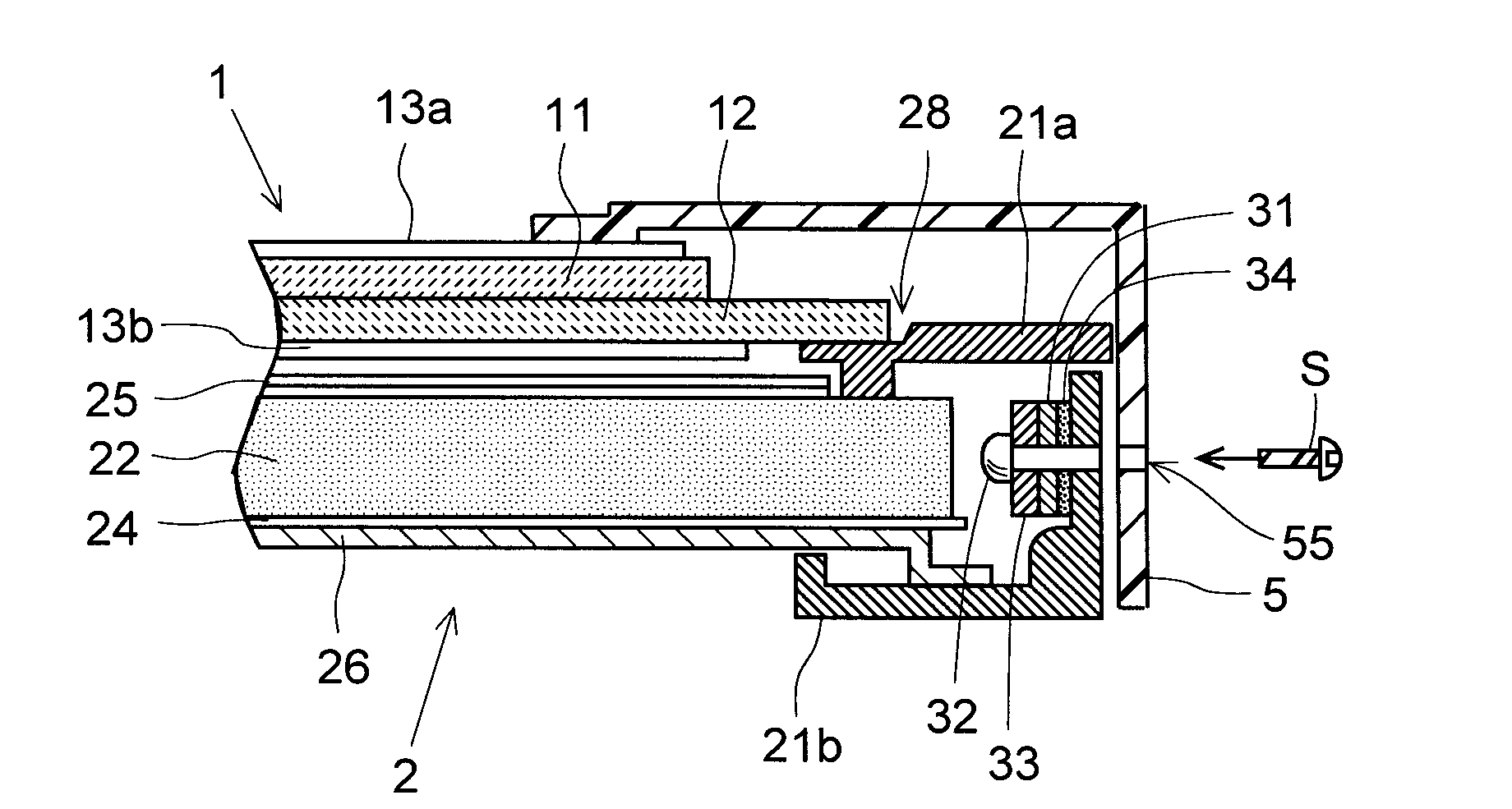
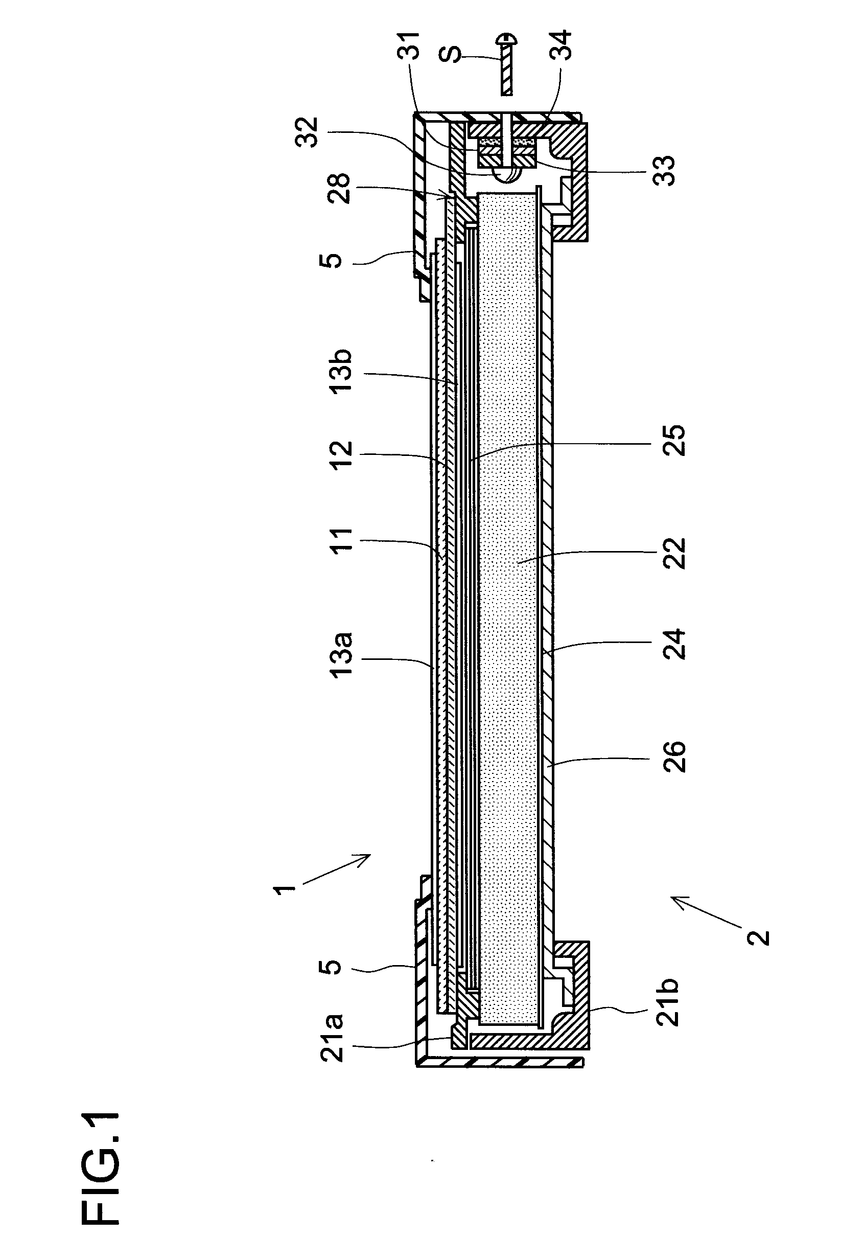
[0048]FIG. 1 is a sectional schematic view showing an example of a liquid crystal display device (planar display device) and a backlight device. The liquid crystal display device shown in FIG. 1 includes a backlight device 2 and ...


PUM


Abstract

An FPC (31) on which LEDs (32) are mounted at predetermined intervals in the longitudinal direction is secured to a lower chassis (21b) used also as a heat-dissipating plate through an elastic heat conductive sheet (34). With a retaining plate (33) is overlapped on the mounting surface of the FPC (31), a screw (S) is inserted into the retaining plate (33) from the outside of a bezel (5) to fix the retaining plate. Furthermore, the FPC (31) is held between the retaining plate (33) and the lower chassis (21b).

Description

TECHNICAL FIELD[0001]The present invention relates to a backlight device, and more particularly to a side-lit backlight device employing a point light source.BACKGROUND ART[0002]In non-self-luminous display devices such as liquid crystal display devices, so called backlight devices that illuminate display panels from behind are generally provided. These backlight devices divide into a direct-lit type, a side-lit type, a planar light source type, etc., and the side-lit type is widely adopted as display devices are made slimmer and lighter.[0003]In a side-lit backlight device, light from a light source is led into a light guide plate through a side surface thereof and is made to travel inside the light guide plate by total reflection; in addition, light is partly reflected on a reflective sheet fitted on a back surface of the light guide plate; thus light emerges through a main surface of the light guide plate to act as a planar light source, to thereby illuminate a back surface of a ...

Claims


Application Information

Patent Timeline
IPC IPC(8): F21V7/04F21V29/00
CPCG02B6/0085
Inventor HAMADA, TETSUYA
Owner SHARP KK
Why Eureka
Try Eureka