

Coating dispersion machine with cooling function
A technology for dispersing machines and coatings, applied to mixers with rotating containers, mixers with rotating stirring devices, mixers, etc., can solve problems such as poor mixing efficiency, limited use range, adjustment, etc., and achieve improved dispersion efficiency, Improve the scope of application and improve the effect of dispersion effect
- Summary
- Abstract
- Description
- Claims
- Application Information
AI Technical Summary
Problems solved by technology
Method used
Image

Examples
Embodiment 1
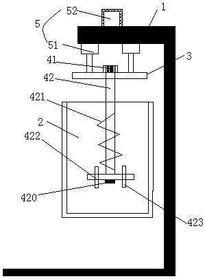
[0023] Such as Figure 1-4 As shown, a paint dispersing machine with cooling function includes a support 1, a dispersion bucket 2, a top plate 3, and a stirring mechanism fixed on the top plate 3. The stirring mechanism includes a first motor 41 and a stirring shaft 42, and the top plate 3 is also fixed. There is a lifting mechanism 5, and the lifting mechanism 5 includes a hydraulic cylinder 51 fixed on the top plate 3 and a controller 52 for controlling the movement of the hydraulic cylinder 51, and the hydraulic cylinder 51 and the controller 52 are fixed on the support 1; There is a pressure sensor 421, and the pressure sensor 421 is electrically connected with the controller 52;
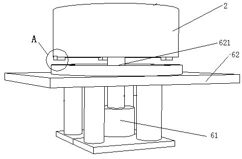
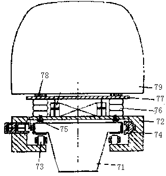
[0024] The bottom of dispersion bucket 2 is provided with rotating mechanism 6, and rotating mechanism 6 comprises second motor 61, support plate 62 and the suspension mechanism that is arranged on the support plate 62, and support plate 62 center is provided with a central hole 621, and the out...
Embodiment 2
[0027] On the basis of a paint disperser with cooling function in Embodiment 1, it is further optimized. The stirring shaft 42 is provided with a helical blade 421 and a sawtooth disc impeller 422, and the helical blade 421 spirally surrounds the outer surface of the stirring shaft 42. Above, the serrated disc impeller 422 is fixedly connected to the bottom of the stirring shaft 42 .
Embodiment 3
[0029] On the basis of a paint disperser with cooling function in Embodiment 2, a number of blades 423 are evenly distributed on the bottom of the sawtooth disc impeller 422 along the circumferential direction of the sawtooth disc impeller 422 .
PUM
 Abstract
Description
Claims
Application Information