Supercharge Your Innovation With Domain-Expert AI Agents!

Illumination device

a technology of illumination device and lightemitting diode, which is applied in the direction of semiconductor devices for light sources, lighting and heating apparatus, and light support devices. it can solve the problems of low lighting efficiency, short service life, and the likelihood of environmental pollution of discarded fluorescent tubes, so as to improve heat dissipation efficiency and reduce costs. the effect of cos

Inactive Publication Date: 2013-09-12
KUN HSIN TECH +1
View PDF12 Cites 4 Cited by
  • Summary
  • Abstract
  • Description
  • Claims
  • Application Information

AI Technical Summary

Benefits of technology

The invention aims to create an illumination device that is more cost-effective, efficient in heat dissipation, and faster in production. It improves productivity and lighting efficiency compared to existing technologies on the market.

Problems solved by technology

Conventional fluorescent tube illumination has the following disadvantages; service life is short; lighting efficiency is low; and discarded fluorescent tubes are likely to pollute the environment.
However, due to the need for heat dissipation, the heat dissipation structure contributes to a significant increase in the manufacturing cost of current LED lamp assembly.
As a result, the manufacturing cost of LED dies having illumination function only accounts for less than 10% of the overall cost of the illumination device, so having such structure is highly uneconomical.

Method used


Image

  • Illumination device
  • Illumination device
  • Illumination device

Examples


Embodiment Construction

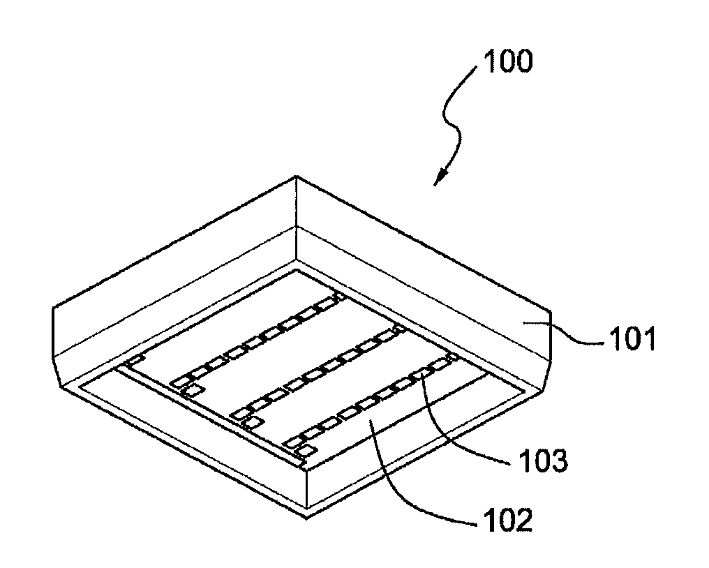
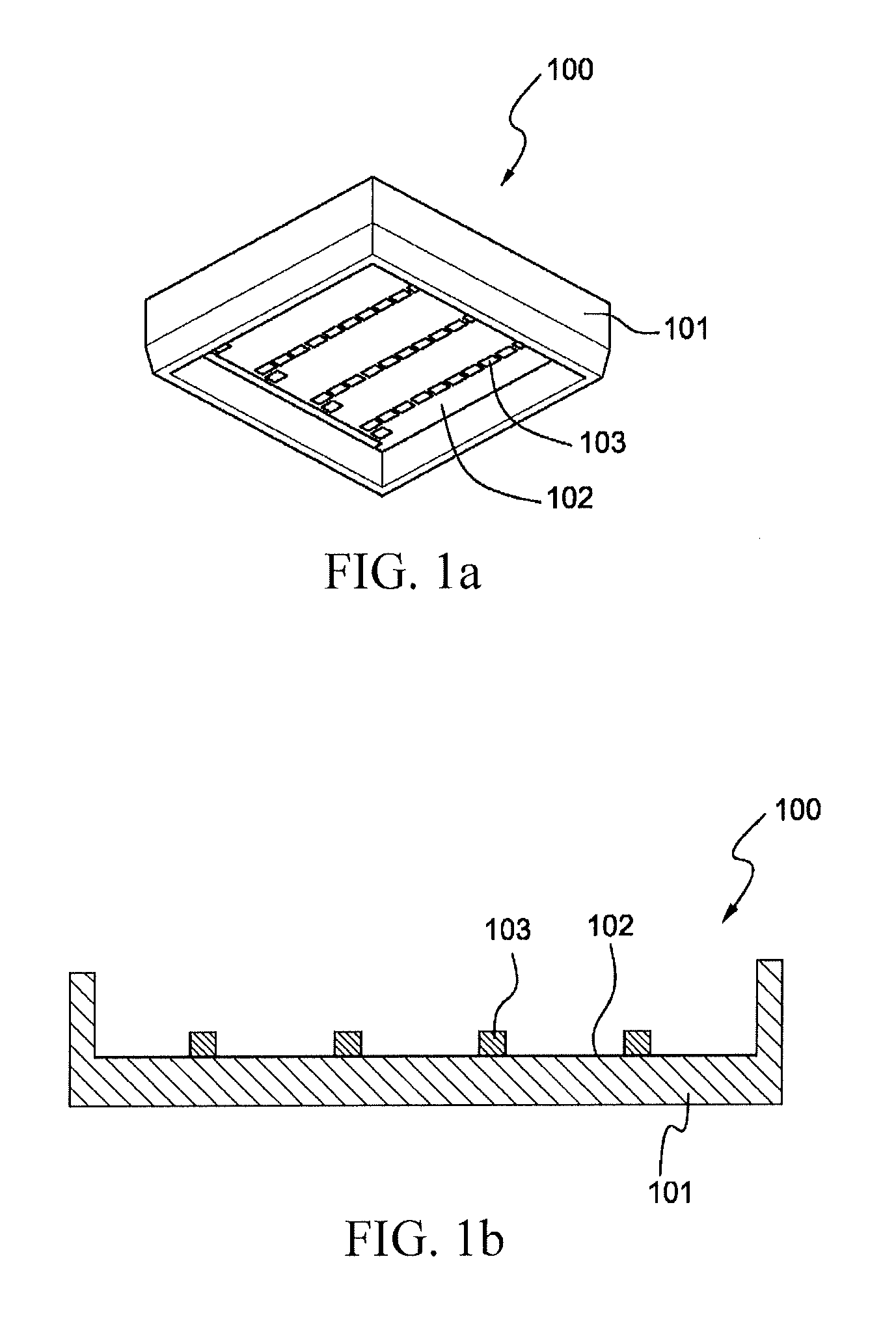
[0019]An embodiment of an illumination device according to the subject invention is shown in FIG. 1a. An illumination device 100 includes a lamp holder 101 having a base (namely a bottom surface) 102, and a plurality of LED dies 103 directly bonded on the base 102. FIG. 1b is a sectional view of the illumination device 100 of FIG. 1a. Configuration of the illumination device of the subject invention can be better understood when making reference to sectional view.

[0020]In the illumination device according to the subject invention, based on design requirements, the plurality of LED dies 103 may be directly bonded on the base 102 of the illumination device, such as randomly configured on the base 102 (for example, in a manner of series connection, parallel connection, or series-parallel connection) in compliance with a luminance requirement or a circuit configuration requirement. In addition, since the configured LED dies are directly bonded on the base 102, the base 102 itself can be...


PUM

PropertyMeasurementUnit
thicknessaaaaaaaaaa
side lengthaaaaaaaaaa

Abstract

The subject invention relates to an illumination device, comprising a lamp holder having a base; and a plurality of LED dies directly bonded on the base. The structure of the illumination device of the subject invention can eliminate unnecessary elements, reduce process time and further improve lighting efficiency.

Description

BACKGROUND OF THE INVENTION[0001]1. Field of the Invention[0002]The subject invention relates to an illumination device, and more particularly to light-emitting diode (LED) illumination device.[0003]2. Description of the Related Art[0004]Conventional fluorescent tube illumination has the following disadvantages; service life is short; lighting efficiency is low; and discarded fluorescent tubes are likely to pollute the environment. LED is power-saving and to has high lighting efficiency, which can resolve the problems associated with conventional fluorescent tubes.[0005]The dimension of fluorescent lamps has fixed for many years, and in order to minimize cost associated with the switch to LED, for example when altering ceiling decoration, new LED lamps have always been developed in compliance with the existing dimension of the fluorescent lamps. For example, ROC Patent No. M413802 (LED illumination tube) has disclosed LED illumination applicable to fluorescent lamps with existing di...

Claims


Application Information

Patent Timeline
Patent Type & Authority Applications(United States)
IPC IPC(8): F21V13/02F21V29/00F21V7/00
CPCF21V13/02F21V7/00F21V3/0463F21V7/005F21V9/16F21V29/89F21Y2105/001F21V3/0481F21V29/507F21V29/70F21Y2101/02F21Y2105/10F21Y2115/10F21V3/08F21V3/12F21V13/08F21V1/17
Inventor LIN, KUN CHUAN
Owner KUN HSIN TECH
Features
  • R&D
  • Intellectual Property
  • Life Sciences
  • Materials
  • Tech Scout
  • Unparalleled Data Quality
  • Higher Quality Content
  • 60% Fewer Hallucinations
Learn More