Measurement device for identifying electromagnetic interference source, method for estimating the same, and computer readable information recording medium enabling operations thereof

a measurement device and electromagnetic interference technology, applied in measurement devices, instruments, computing, etc., can solve the problems of difficult to pinpoint the position of the interference source, the potential interference source cannot be effectively identified, and the interference source cannot be identified, so as to achieve accurate and efficient determination of the location, localized and efficient countermeasures

Inactive Publication Date: 2013-09-12
TAIYO YUDEN KK
View PDF0 Cites 15 Cited by
  • Summary
  • Abstract
  • Description
  • Claims
  • Application Information

AI Technical Summary

Benefits of technology

[0015]The present invention was made in view of the above-mentioned problems, and aims to provide a measurement device capable of identifying a source of interference electromagnetic wave with regard to an EMC problem caused by interference electromagnetic waves emitted from an electronic device, a method of identifying the same, and an information recording medium having computer programs for performing operations thereof. In one mode of the invention, near-field electromagnetic field of the source is effectively and efficiently measured and analyzed.
[0020]According to the present invention, it becomes possible to identify a source that emits interference electromagnetic waves having temporal characteristics that are similar to the temporal signal characteristics of the interference power received at an antenna under influence of interference. This enables more accurate and efficient determination of the location and / or identification of the interference source(s), and allows more localized and efficient countermeasures for the EMC problems to implement.

Problems solved by technology

However, with the electromagnetic field distribution that shows the intensity only and that does not take into account the temporal change thereof, when signals having the same frequency are present at a plurality of locations, the potential interference source cannot be identified effectively.
However, if signals outputted from a plurality of output terminals of the IC are synchronized with the same operating clock signal, electromagnetic fields of the same frequency are generated, and therefore, the interference source cannot be identified just by measuring the intensity of the electromagnetic field emitted from each output terminal of the IC.
As described above, when the measurement was conducted only for the distribution of the intensity of the emitted electromagnetic fields, signals that are irrelevant to an interference source in the intra-system EMC or to fundamental noise that results in unwanted emission EMI were also detected, which made it difficult to pinpoint the position of the interference source.

Method used


Image

  • Measurement device for identifying electromagnetic interference source, method for estimating the same, and computer readable information recording medium enabling operations thereof
  • Measurement device for identifying electromagnetic interference source, method for estimating the same, and computer readable information recording medium enabling operations thereof
  • Measurement device for identifying electromagnetic interference source, method for estimating the same, and computer readable information recording medium enabling operations thereof

Examples


embodiment 1

[0049 will be described first.

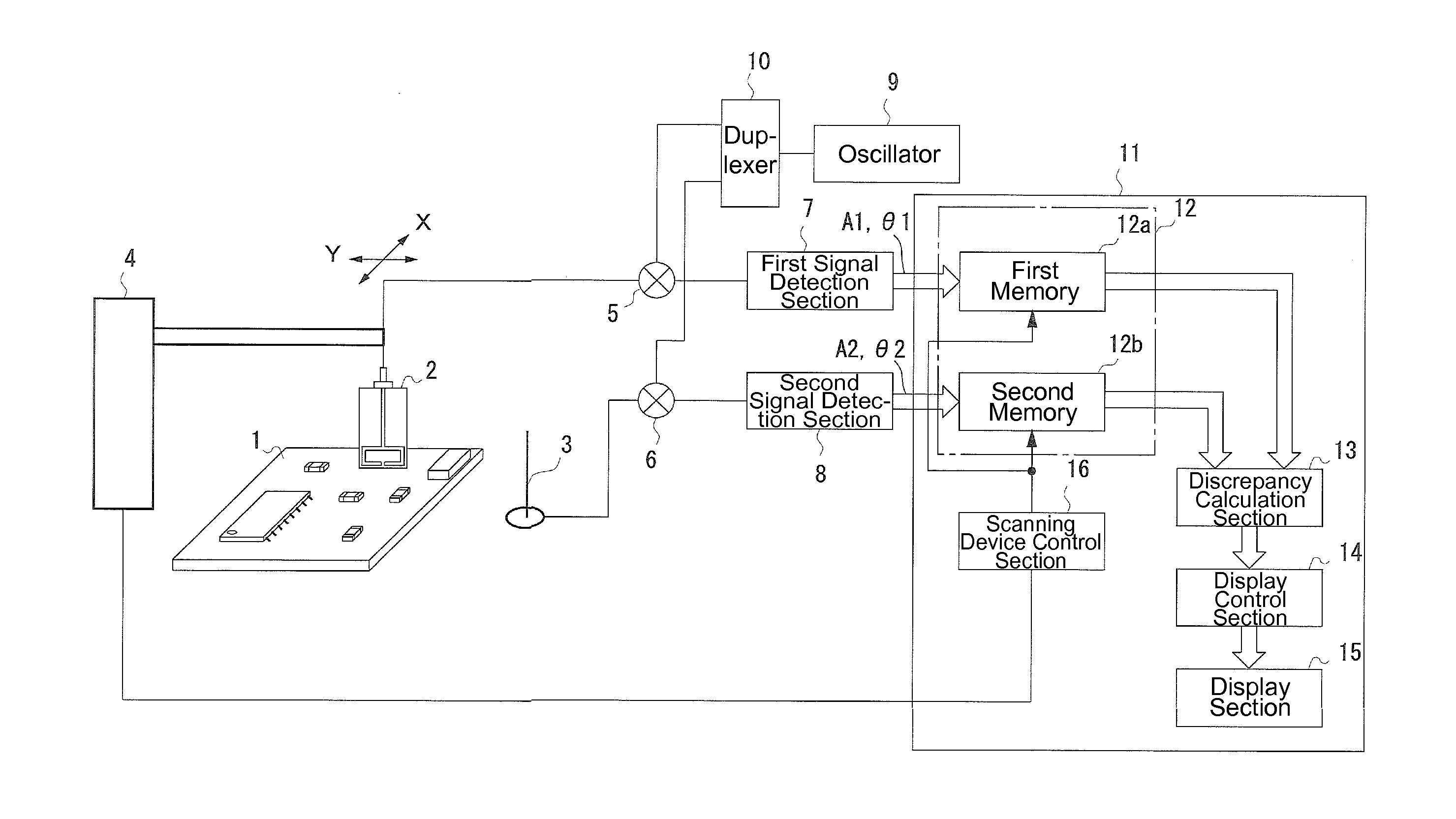
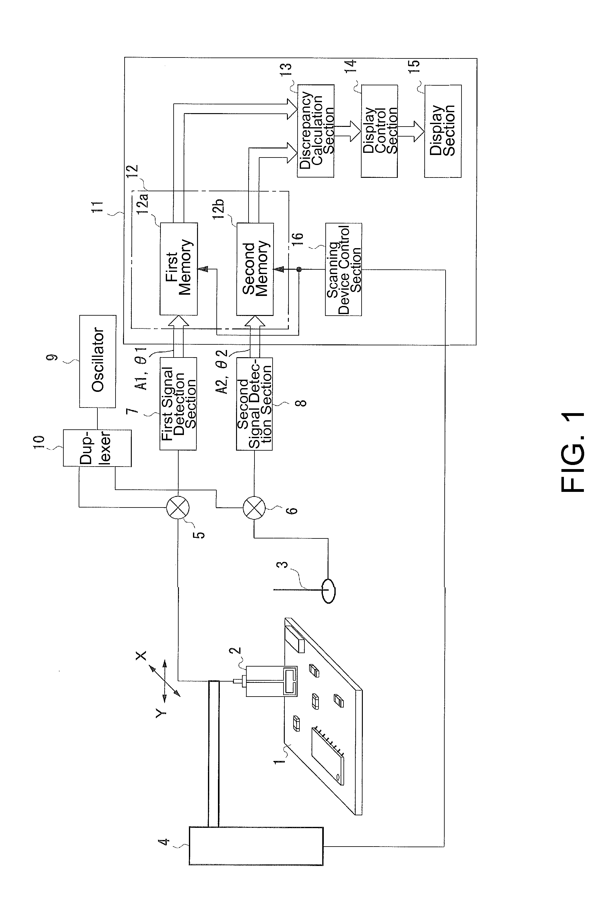
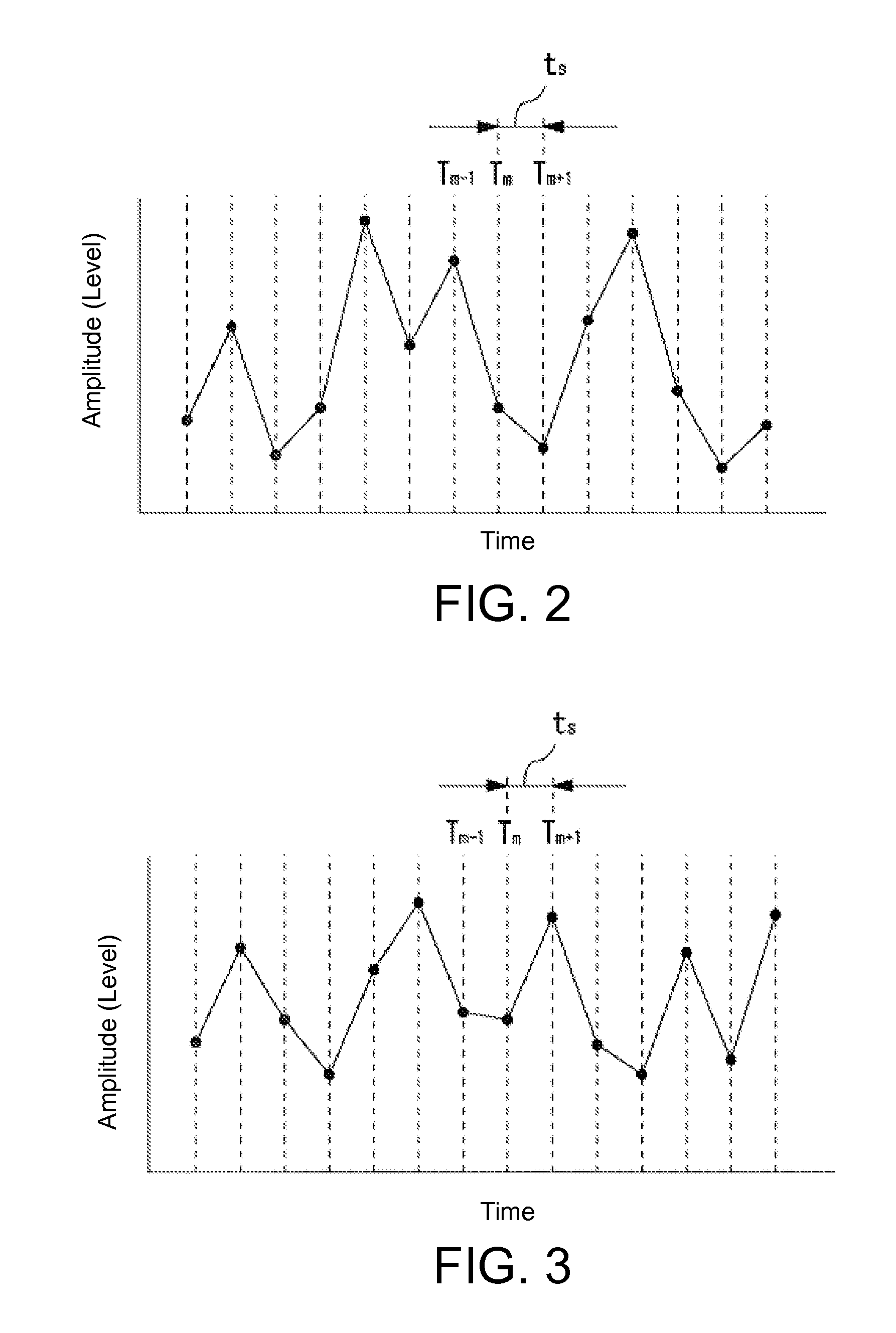
[0050]In Embodiment 1, a sensor for detecting electromagnetic waves is moved across a measurement area of an electronic device emitting the interference electromagnetic waves. An exemplary device of Embodiment 1 identifies a vicinity of a particular sensor position as a source of interference electromagnetic wave, when a temporal waveform of the amplitude of an electromagnetic wave detected by the sensor at that sensor position substantially coincides with a temporal waveform of the amplitude of an electromagnetic wave received by an antenna under interference. Here, the temporal changes in the amplitudes of the received electromagnetic waves are compared, and the degree of discrepancy at each of the respective positions of the sensor is calculated in order to identify the source location / source itself.

[0051]For example, with respect to the changes in the amplitudes of the signals of received electromagnetic waves over the course of time, when the signa...

embodiment 2

[0098]Next, Embodiment 2 of the present invention will be explained.

[0099]The device configuration of Embodiment 2 is substantially the same as that of Embodiment 1 above. Embodiment 2 differs from Embodiment 1 in that the degrees of discrepancy as the measurement results are displayed in the display section 15 as a map. That is, the degrees of discrepancy are categorized into a plurality of levels, and using different display colors or shades for the respective levels, the degrees of discrepancy on the plane (XY plane) of the electronic device 1 are displayed on a monitor screen of the display section 15.

[0100]An operation of the computer device 11 in this case will be explained with reference to a flowchart shown in FIG. 9.

[0101]When the measurement is started, the computer device 11 performs the following steps SB1 to SB9, while changing the positions of the sensor 2.

[0102]That is, for a give position of the sensor 2, the positional information of the sensor 2 and the output data...

embodiment 3

[0110]Next, Embodiment 3 of the present invention will be explained.

[0111]In Embodiment 3, the phrase values described above are used in the determination of the location of the source of the interfering electromagnetic wave. That is, a device of Embodiment 2 identifies, as the location of a source of interference electromagnetic waves, a position near a sensor position at which a difference between a phase of electromagnetic wave received by the antenna under interference 3 and a phase of electromagnetic wave detected at the sensor position by the sensor, which moves across a vicinity of the electronic device emitting the interference electromagnetic wave, remains as substantially the same value over a prescribed measurement period. Here, the phase difference between the received signals of the electromagnetic waves, which are inputted into two input sections, is determined, and the stability in time of the phase difference is used as the degree of coincidence in order to identify ...


PUM


Abstract

With regard to EMC problems resulting from interference electromagnetic wave emitted from a subject electronic device, a source of interference electromagnetic wave is accurately located by measuring near-field electromagnetic wave emitted from the subject electronic device. The waveform of an electromagnetic wave received by an antenna under interference is compared with the waveform of an electromagnetic wave detected by a sensor, which moves across a vicinity of the subject electronic device, and when the temporal changes in amplitudes of these waveforms coincide with each other, or when a phase difference between the signals is found fairly constant over time, the position of the sensor at which such condition is found and / or the vicinity thereof is identified as the location of a source of the interference electromagnetic wave.

Description

[0001]This application claims the benefit of Japanese Application No. 2011-190268 filed in Japan on Sep. 1, 2011, which is hereby incorporated by reference in its entirety.BACKGROUND OF THE INVENTION[0002]1. Field of the Invention[0003]The present invention relates to a measurement device that identifies a source of interference electromagnetic waves with regard to an EMC problem caused by interference electromagnetic waves emitted from an electronic device, a method of identifying the same, and to an information recording medium having computer programs for performing operations thereof. In one mode of the invention, near-field electromagnetic field of the source is effectively and efficiently measured and analyzed.[0004]2. Description of Related Art[0005]In recent years, sophisticated portable terminals are equipped with a semiconductor in which multiple functions such as a DC-DC converter with a plurality of channels, a power saving function, and a protective circuit are integrat...

Claims


Application Information

Patent Timeline
Patent Type & Authority Applications(United States)
IPC IPC(8): G01R31/08
CPCG01R31/002G01R31/088
Inventor KAZAMA, SATOSHITUTAGAYA, HIROSHI
Owner TAIYO YUDEN KK
Why Eureka
Try Eureka