Screen printer

a screen printer and printing technology, applied in printing, coatings, inking apparatus, etc., to prevent paste effluence and ensure stability of screen mask print width, the effect of preventing paste effluence to the outside of the print width

Active Publication Date: 2013-09-19
PANASONIC INTELLECTUAL PROPERTY MANAGEMENT CO LTD
View PDF1 Cites 14 Cited by
  • Summary
  • Abstract
  • Description
  • Claims
  • Application Information

AI Technical Summary

Benefits of technology

[0008]According to the present invention, a pressing mechanism that presses against a screen mask a dam member which prevents effluence of paste to the outside of a print width on the screen mask has a guide shaft that is placed in parallel to a corresponding squeegee and that guides a direction of movement of the dam member during pre

Problems solved by technology

Since the paste dislodged outside the width of the substrate stays behind without being scraped up by the squeegee and is susceptible to flection because an

Method used


Image

  • Screen printer
  • Screen printer
  • Screen printer

Examples


Embodiment Construction

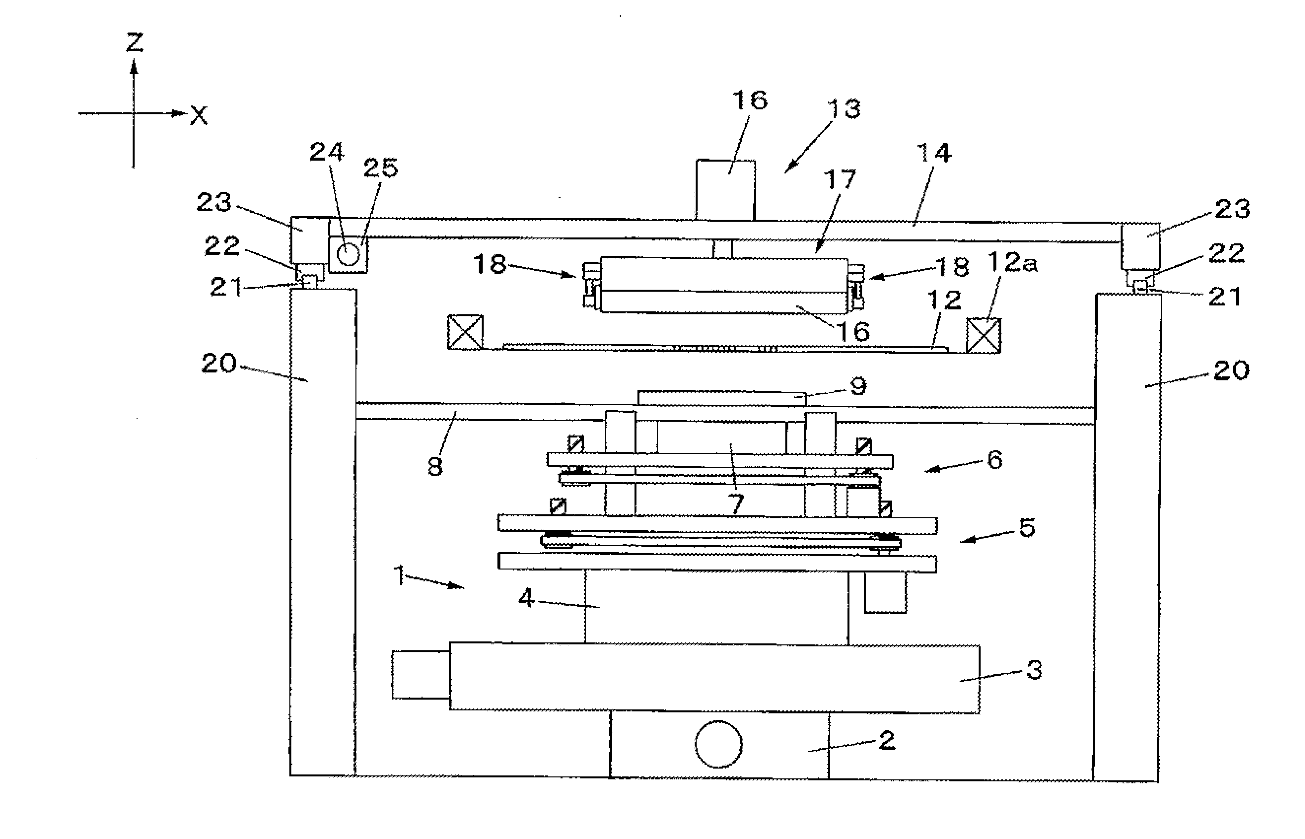
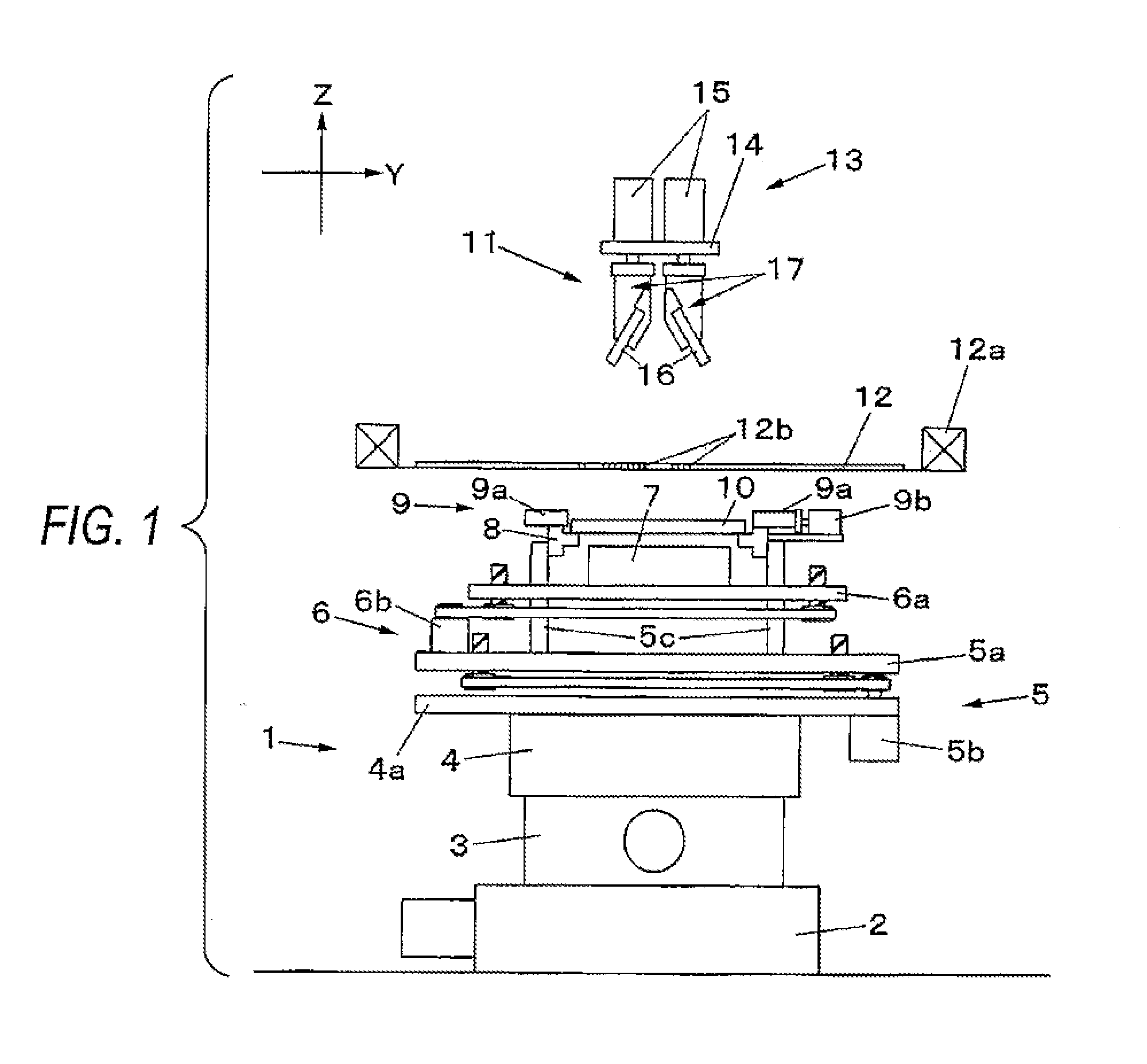
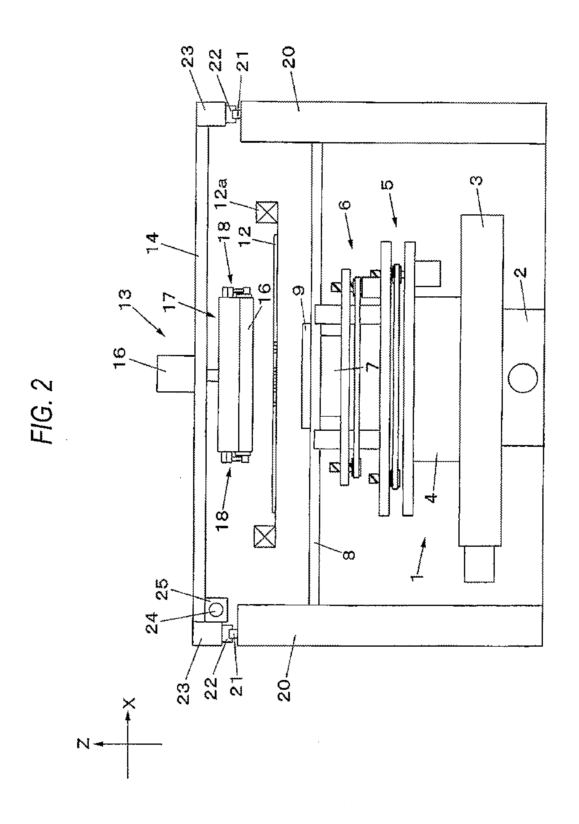
[0018]An embodiment of the present invention is now described by reference to the drawings. First, a structure of a screen printer is described by reference to FIGS. 1, 2, 3(a), and 3(b). In FIG. 1, the screen printer is made up of a substrate positioning section 1 and a screen printing mechanism 11 placed above the substrate positioning section 1. The substrate positioning section 1 is assembled by placing, one on top of the other and in order from the bottom, a Y-axis table 2, an X-axis table 3, and a O-axis table 4 in combination with a first Z-axis table 5 and a second Z-axis table 6 to be additionally placed in this order on the O-axis table 4.

[0019]A configuration of the first Z-axis table 5 is described. A horizontal base plate 5a is held in a vertically movable manner, by an elevation guide mechanism (omitted from the drawings), on an upper surface side of a similarly horizontal base plate 4a put on an upper surface of the O-axis table 4. The base plate 5a is moved up and do...


PUM


Abstract

A pressing mechanism that presses a dam member 30 against a screen mask 12 has a guide shaft 32 that guides a direction of movement of the dam member 30 during pressing operation and a compression spring 33 that forces the dam member 30 in an axial direction of the guide shaft 32. A printing pressure value at which the dam member 30 is pressed against the screen mask 12 is made stable, to thus make stable an effect of preventing effluence of the paste to the outside of a print width on the screen mask 12.

Description

TECHNICAL FIELD[0001]The present invention relates to a screen printer that prints a substrate with paste, like cream solder and conductive paste.BACKGROUND ART[0002]Screen printing has hitherto been employed in an electronic component mounting process as a method for printing a substrate with paste, like cream solder and conductive paste. The method includes setting on a substrate a screen mask which has pattern holes aligned to locations of print targets and slidably moving a squeegee over the screen mask supplied with paste, thereby printing the substrate with the paste through the pattern holes. During screen printing, the paste supplied over the screen mask is scraped up with the squeegee, to thus be supplied over an entire print width of the substrate. During squeegeeing, the paste is scraped up in a direction of movement of the squeegee, being gradually shoved outside along a surface of the squeegee. Since the paste dislodged outside the width of the substrate stays behind wi...

Claims


Application Information

Patent Timeline
IPC IPC(8): B41F15/44
CPCB41F15/0881B41F15/36B41F15/423B41P2215/50H05K3/1233B41F15/42B41F15/44B41F15/40B41M1/12H05K3/1216H05K3/3484H05K3/3485B41F15/08H05K3/34
Inventor KOBAYASHI, HIROKIMURAKAMI, TOSHIYUKI
Owner PANASONIC INTELLECTUAL PROPERTY MANAGEMENT CO LTD
Why Eureka
Try Eureka