

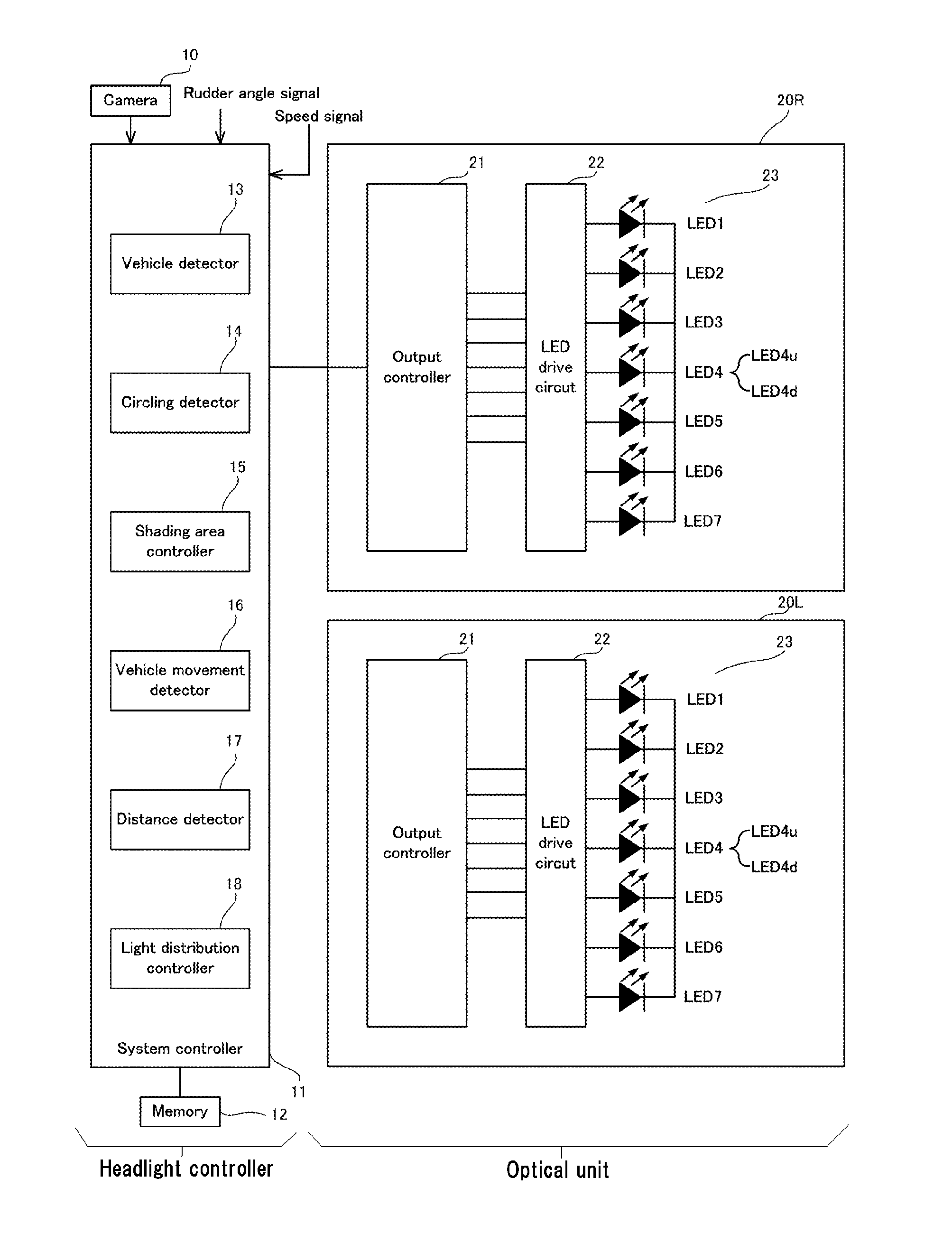
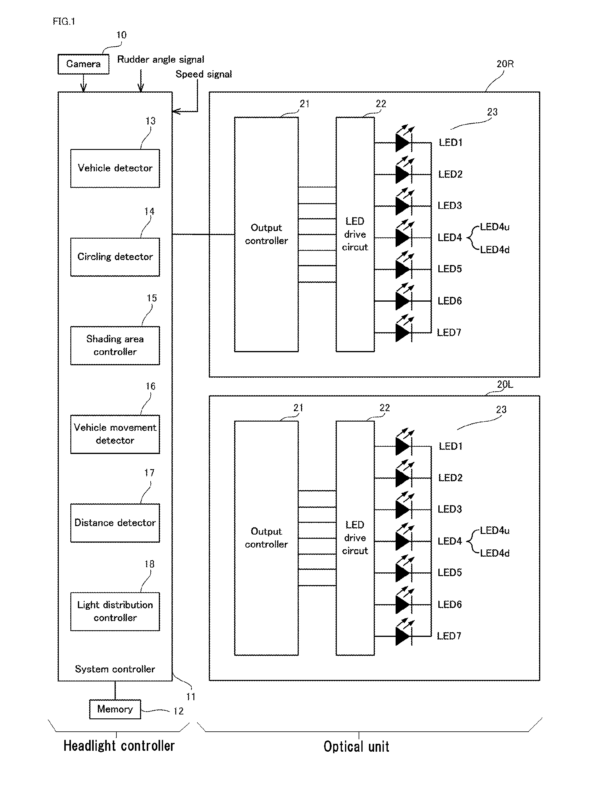
Headlight controller, optical unit and vehicle headlight
a headlight controller and optical unit technology, applied in the field of headlight controllers, optical units and vehicle headlights, can solve the problems of difficult design and difficult to reduce the size of the headlight, and achieve the effects of simple structure, easy driving, and high reliability
- Summary
- Abstract
- Description
- Claims
- Application Information
AI Technical Summary
Benefits of technology
Problems solved by technology
Method used
Image

Examples
exemplary embodiment 1
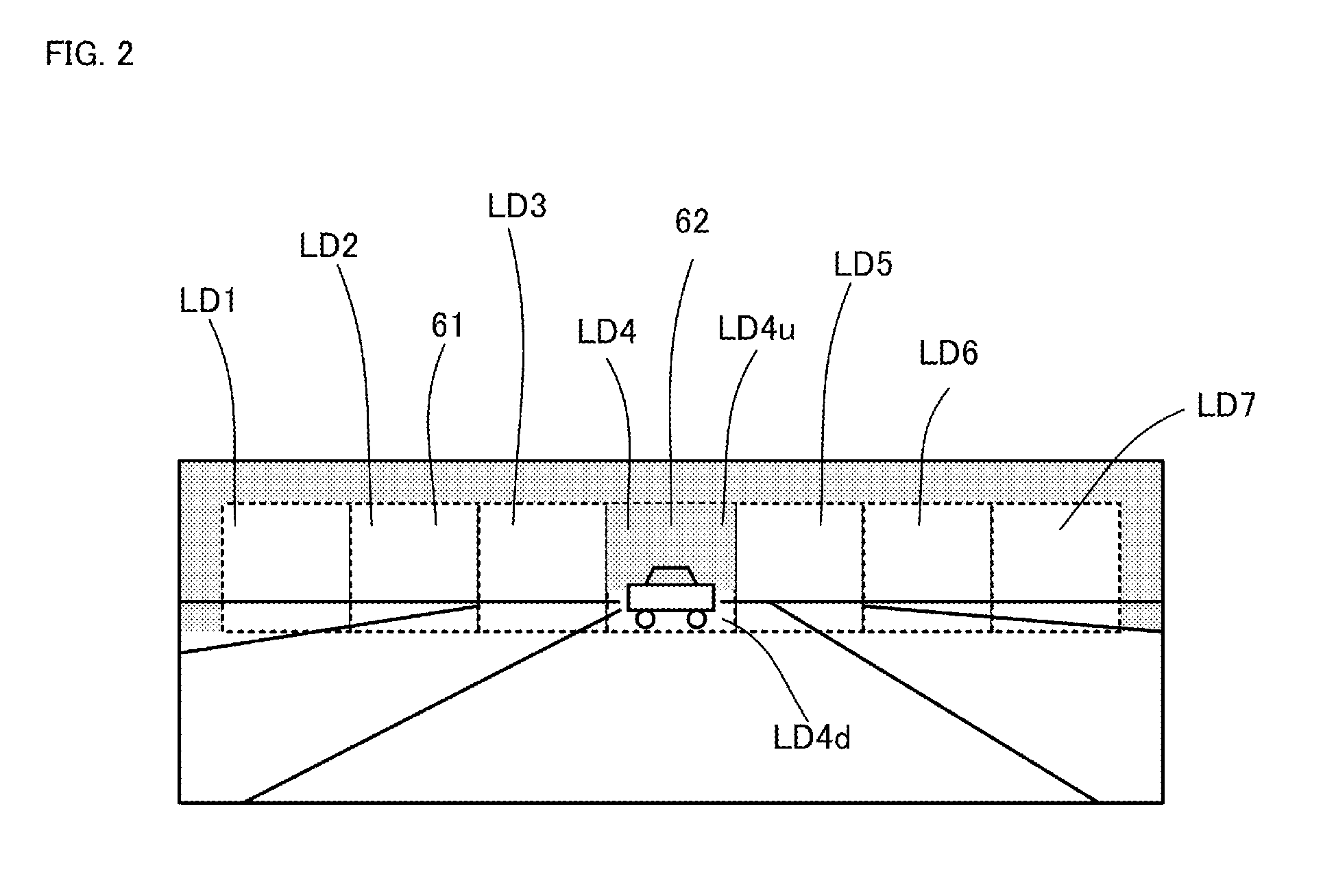
[0071]Meanwhile, a light distribution pattern of Exemplary embodiment 1 shown in FIG. 3b can be formed by the vehicle headlight, which employs a calculating method for a case where the own vehicle takes a right turn. The calculating method can employ an algorithm for taking a right turn and therefore can estimate the width of the forward vehicle at a relative wide width, because the calculating method is based upon a turning radius of the own vehicle. Thus, the disclosed subject matter can provide a vehicle headlight that can prevent the optical unit 20R and 20L from giving a glare type light to the forward vehicle including the driver seat, even when the subject vehicle takes a right turn, as shown in FIG. 3b.
[0072]FIGS. 4a and 4b are schematic top / front views depicting Comparative embodiment 2 and Exemplary embodiment 2 of light distribution patterns projected from the optical unit 20R and 20L when a forward vehicle moves rightward on a same driving lane as the subject vehicle us...
exemplary embodiment 2
[0074]On the contrary, a light distribution pattern of Exemplary embodiment 2 can be formed by the vehicle headlight, which can employ a calculating method for a case where the forward vehicle moves rightward in response to the image data output from the camera 10. The calculating method can employ an algorithm including a moving direction of the forward vehicle, and therefore can revise a shape of the shading area 62, because the calculating method can be based upon a relative angle of the forward vehicle with respect to the subject vehicle. Thus, the disclosed subject matter can provide vehicle headlights that can prevent the optical unit 20R and 20L from emitting a glare type light to the forward vehicle including the driver seat, even when the forward vehicle suddenly moves rightward due to its lane change, furthermore while providing a favorable light distribution for a driver of the own vehicle, as shown in FIG. 4b.
[0075]The cases where the forward vehicle takes a right turn ...
PUM
 Abstract
Description
Claims
Application Information