Particle image velocimetry system for three-dimensional space

a technology of velocimetry system and particle image, which is applied in the direction of fluid speed measurement, instruments, devices using optical means, etc., can solve the problems of increasing equipment cost, difficult to ensure, and requiring a lot of time and manpower for setting up cameras, so as to improve measurement accuracy and reduce the number of cameras

Active Publication Date: 2013-09-19
HONDA MOTOR CO LTD
View PDF1 Cites 28 Cited by
  • Summary
  • Abstract
  • Description
  • Claims
  • Application Information

AI Technical Summary

Benefits of technology

[0009]The present invention has been accomplished in light of the above-mentioned circumstances, and it is an object thereof to provide enhanced measurement precision while reducing the number of cameras when measuring a three-dimensional velocity field around an object using tomographic theory.
[0011]In this embodiment, tracer particles included in a flow field around the object are illuminated with laser light, and an image thereof is taken by imaging means at two times separated by a very small period of time. The position of tracer particles in the three-dimensional space is calculated by tomography from the images at the two times, the velocity field of three velocity components in the three-dimensional space can be measured from the difference between the positions of tracer particle at the two times and, moreover, the use of tomography enables an unsteady velocity field in the three-dimensional space to be measured directly without stacking velocity fields in two-dimensional space on one another.
[0012]Since the imaging device include the imaging lens, which takes an image of tracer particles, the compound-eye lens formed from the large number of monocular lenses, which take images of the image taken by the imaging lens, and the light receiving element, which subjects the image taken by the monocular lens to photoelectric conversion, each of the plurality of monocular lenses forming the compound-eye lens of one imaging device functions as one imaging device. One imaging device can be made to exhibit the same function as that of a plurality of imaging device. This not only enables the measurement precision to be enhanced by suppressing the influence of ghost particles while greatly reducing the equipment cost by minimizing the number of imaging device, but also enables a space for installing the imaging device to be easily ensured. Moreover, if a large number of imaging device are used, not only is there a problem that they require much time and manpower for setting up, but there is also a possibility that the measurement precision will be degraded due to displacement of an axis of each of the imaging device caused by vibration, etc. However, since the imaging device having the compound-eye lens is used, setting up becomes easy and, moreover, since the positional relationship between the large number of monocular lenses of the compound-eye lens does not change, the measurement precision can be ensured.
[0014]With such an embodiment, when the focal length of the imaging lens is fd, the distance from the focal point of the imaging lens to the compound-eye lens is d, and the distance from the imaging lens in the optical axis direction is x, a region satisfyingfd<x<fd+(fd2 / d)is defined as the imaging region, it becomes possible to take images of individual tracer particles present in the imaging region simultaneously by a large number of monocular lenses, thereby further enhancing the measurement precision.

Problems solved by technology

Meanwhile, the arrangement described in Non-Patent Document 1 above has the problem that, since images of the region illuminated with volume illumination are taken from different directions by means of a plurality of cameras, when the position of tracer particles in three-dimensional space is calculated from the obtained images, a tracer particle (ghost particle) that is not actually present is recognized as if it were present.
However, increasing the number of cameras not only causes the equipment cost to increase greatly but also makes it difficult to ensure that there is a space for installing the cameras and, moreover, there is a problem that it requires much time and manpower for setting up the cameras.
Moreover, if a large number of imaging device are used, not only is there a problem that they require much time and manpower for setting up, but there is also a possibility that the measurement precision will be degraded due to displacement of an axis of each of the imaging device caused by vibration, etc.

Method used


Image

  • Particle image velocimetry system for three-dimensional space
  • Particle image velocimetry system for three-dimensional space
  • Particle image velocimetry system for three-dimensional space

Examples


Embodiment Construction

[0025]An embodiment of the present invention is explained below by reference to FIG. 1 to FIG. 6.

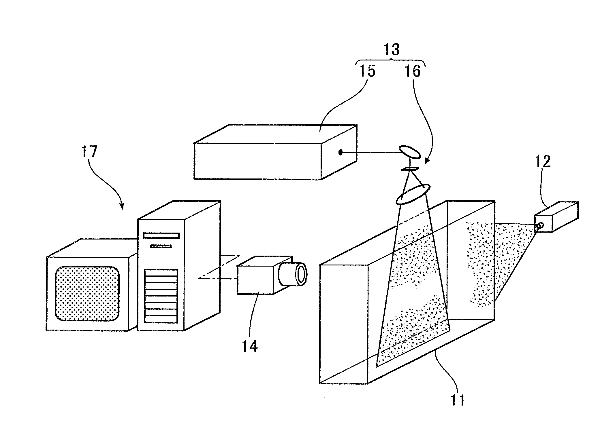
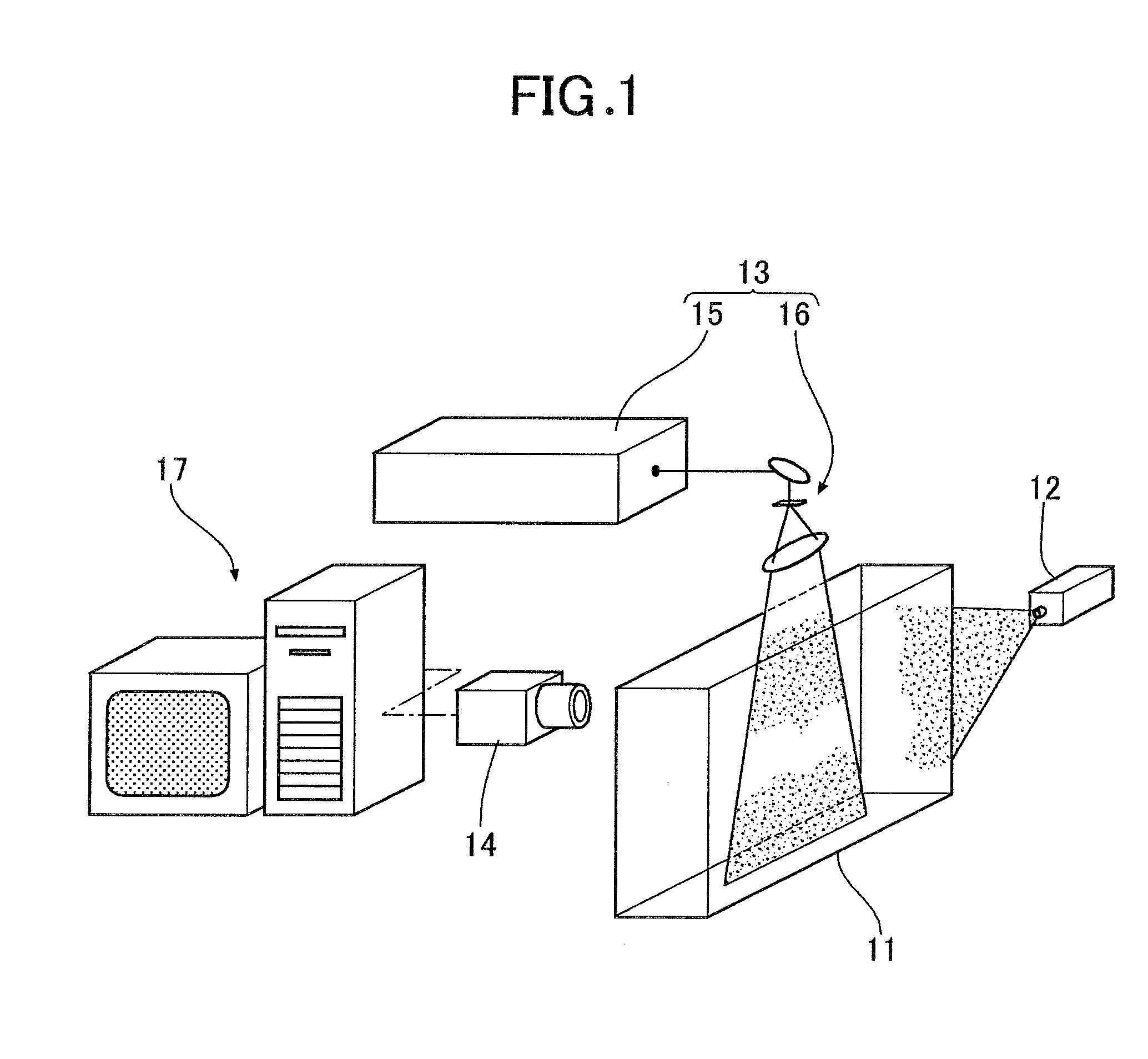
[0026]As shown in FIG. 1, a particle image velocimetry system of the embodiment is used for measuring a three-dimensional velocity field around an object such as an automobile vehicle body. A tracer particle supply unit 12, disposed in an upstream part of a wind tunnel 11 to which a uniform flow of air at a predetermined flow velocity is supplied, supplies microscopic oil droplets (tracer particles) having a diameter of a few μm to the interior of the wind tunnel 11. The uniform flow changes its direction along the surface of the object, thus forming a three-dimensional velocity field. In the case of a closed type wind tunnel 11, at least one part of its wall face is provided with a transparent observation window, and a light source 13 and a CCD camera 14 are disposed at positions where they face the object with the observation window disposed therebetween.

[0027]The light source 13 is fo...


PUM


Abstract

An imaging device can take an image of a flow field including tracer particles includes a compound-eye lens formed from a large number of monocular lenses, which take images of images taken by an imaging lens. Each of the multiple monocular lenses functions as one imaging device. This can enable measurement precision to be enhanced by suppressing the influence of ghost particles, while reducing the equipment cost by minimizing the number of imaging devices. A space for installing the imaging device can easily ensured. If a large number of imaging devices are used, not only do they require time and manpower for setting up, but there is also a possibility that the measurement precision will be degraded due to displacement of an axis of the imaging devices caused by vibration, etc. When the imaging device having the compound-eye lens is used, setup is simplified, and measurement precision can be ensured.

Description

BACKGROUND[0001]1. Field[0002]Embodiments of the present invention relate to a particle image velocimetry system for a three-dimensional space, the system involving illuminating tracer particles flowing around an object with laser light at two times separated by a very small period of time, taking images of the tracer particles illuminated with the laser light by an imaging device, and measuring the velocity field of three velocity components in the three-dimensional space by tomography from the obtained images at the two times.[0003]2. Description of the Related Art[0004]PIV (Particle Image Velocimetry), in which fluid including tracer particles is illuminated with sheet-shaped illumination two times with a predetermined interval therebetween, images of the tracer particles illuminated with the illumination are taken by one imaging means, and the amount of movement of the tracer particles is determined from the images at the two times to thus measure a two-dimensional distribution ...

Claims


Application Information

Patent Timeline
Patent Type & Authority Applications(United States)
IPC IPC(8): G01P5/26
CPCG01P5/26G01P5/22G01P5/001
Inventor FUKUCHI, YUICHI
Owner HONDA MOTOR CO LTD
Why Eureka
Try Eureka