Optical unit and image pickup apparatus

a technology of optical units and pickup apparatuses, applied in the field of optical units and image pickup apparatuses, can solve the problems of large optical distortion and insufficient elimination of aberration, and achieve the effects of reducing optical distortion to a small amount, reducing aberration, and reducing aberration

Inactive Publication Date: 2013-09-19
SONY CORP
View PDF4 Cites 8 Cited by
  • Summary
  • Abstract
  • Description
  • Claims
  • Application Information

AI Technical Summary

Benefits of technology

[0008]The present disclosure provides an optical unit of a wide-angle lens configured of three groups, that is capable of suppressing optical distortion to a small amount, that has favorable optical characteristics, and that is tolerant of reflow. The present disclosure also provides an image pickup apparatus.
[0011]According to the present disclosure, it is achieved an wide-angle lens including three groups, that is capable of suppressing optical distortion to a small amount, that has favorable optical characteristics, and that is tolerant of reflow.

Problems solved by technology

However, optical distortion is large and even the smallest of three Examples has optical distortion of about 15[%] in the wide-angle lens disclosed in Patent Literature 1.
One reason for this is that the first lens has a spherical surface, and therefore, aberration is not sufficiently eliminated.

Method used


Image

  • Optical unit and image pickup apparatus
  • Optical unit and image pickup apparatus
  • Optical unit and image pickup apparatus

Examples


first embodiment

1. First Embodiment

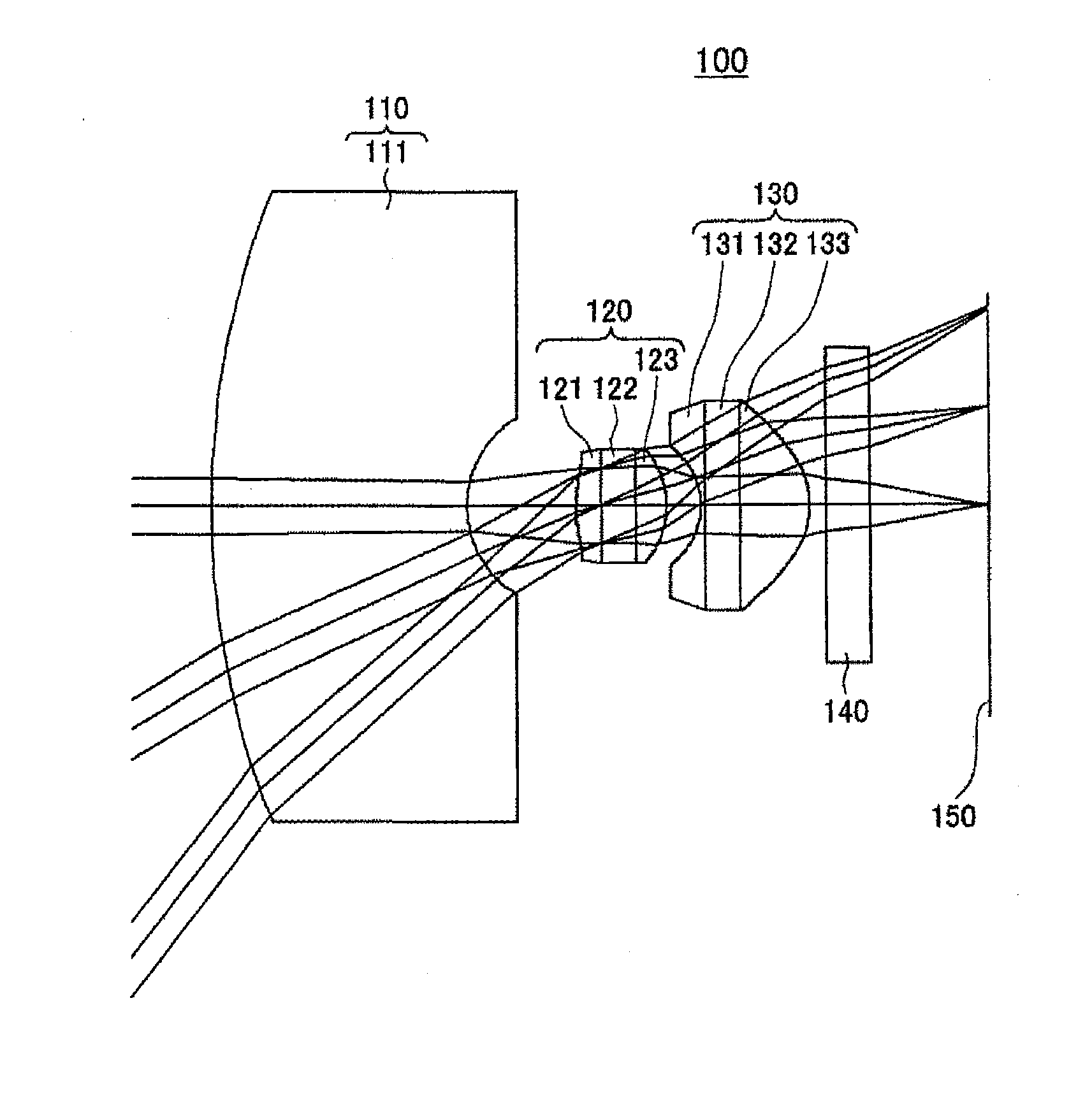
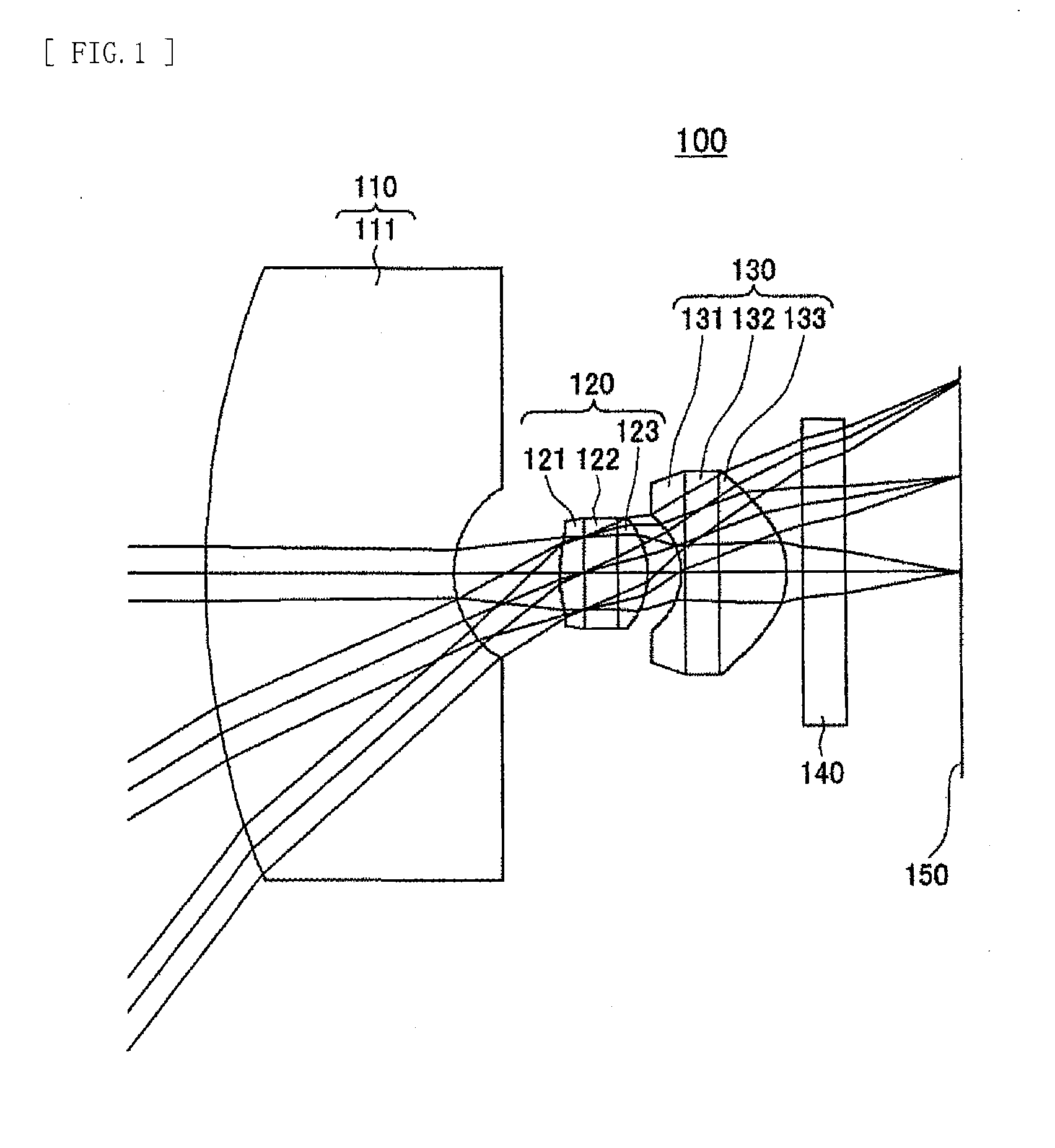
[0023]FIG. 1 is a diagram illustrating a configuration example of an image pickup lens adopting an optical unit according to a first embodiment of the present disclosure.

[0024]An image pickup lens 100 of the present first embodiment includes a first lens group 110, a second lens group 120, a third lens group 130, a cover glass 140, and an image plane 150 that are arranged in order from object plane OBJS toward the image plane as shown in FIG. 1. The image pickup lens 100 is formed as a single focus lens. The first lens group 110, the second lens group 120, and the third lens group 130 form an optical unit.

[0025]In the first embodiment, the second lens group 120 and the third lens group 130 are each formed of a cemented body that includes a plurality of lens elements arranged with a transparent member in between. The first lens group 110 includes only a single first lens element 111.

[0026]The first lens group 110 includes the first lens element 111 that is a glass ...

example 1

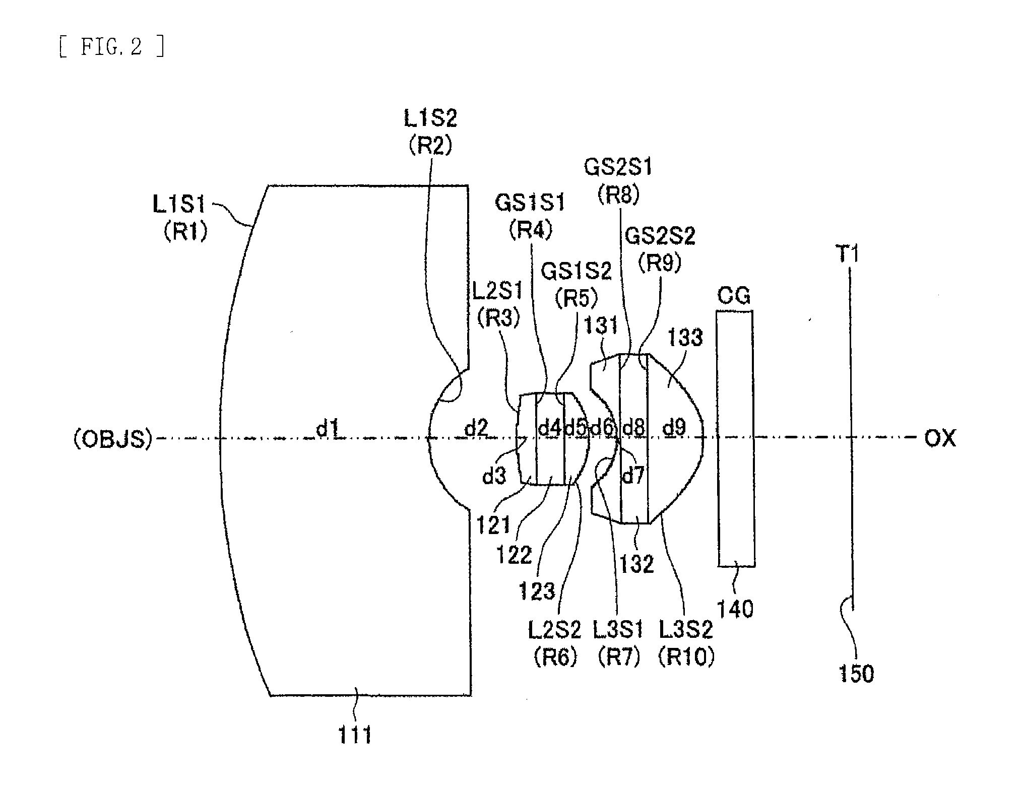
[0053]Table 1, Table 2, Table 3, and Table 4 show respective numeral values of Example 1. The respective numeral values of Example 1 correspond to the image pickup lens 100 in FIG. 1. Example 1 is a design example for a ¼-sized CCD or CMOS imager.

[0054]Table 1 shows a curvature radius (R: mm), a space (d: mm), a refractive index (nd), and a dispersion value (νd) of each of the lens elements, the glass substrates (transparent members), etc. corresponding to the respective surface numbers of the image pickup lens in Example 1.

TABLE 1Lens Configuration Data of Example 1SurfacenumberRdndνdL1S1:9.4653.0001.5264.2L1S2:1.1651.264L2S1:2.1500.2781.5929.6GS1S1:INFINITY0.4001.5264.2GS1S2:INFINITY0.3621.5157.3L2S2:−0.9260.402L3S1:−0.7560.0501.5929.6GS2S1:INFINITY0.4001.5264.2GS2S2:INFINITY0.8041.5157.3L3S2:−0.9110.200CG:INFINITY0.5001.5264.2T1:INFINITY1.406

[0055]Table 2 shows fourth-degree, sixth-degree, eighth-degree, and tenth-degree aspheric surface coefficients of the face L2S1 of the secon...

second embodiment

2. Second Embodiment

[0060]FIG. 4 is a diagram illustrating a configuration example of an image pickup lens according to a second embodiment of the present disclosure.

[0061]An image pickup lens 100A according to the second embodiment shown in FIG. 4 basically includes three groups, that is, a first lens group 110A, a second lens group 120A, and a third lens group 130A, as in the first embodiment. The second lens group 120A and the third lens group 130A are each formed of a cemented body that includes a plurality of lens elements arranged with a transparent member in between also in the second embodiment. The first lens group 110A includes only the single first lens element 111.

[0062]The first lens group 110A includes the first lens element 111 that is a glass spherical lens equivalent to BK7 available from SCHOTT AG that has negative power and has a concave shape facing toward the image plane.

[0063]The second lens group 120A is formed of a cemented body that includes the second lens ...


PUM


Abstract

An optical unit that is configured of a three-group wide-angle lens, that is capable of suppressing optical distortion to a small amount, that has favorable optical characteristics, and that is tolerant of reflow, and an image pickup apparatus are provided. An optical unit 100 includes: a first lens group 110 including a first lens element 111; a second lens group 120 including a second lens element 121, a first transparent member 122, and a third lens element 123 that are arranged in order from object plane toward image plane; and a third lens group 130 including a fourth lens element 131, a second transparent member 132, and a fifth lens element 33 that are arranged in order from the object plane toward the image plane, the first lens group 110, the second lens group 120, and the third lens group 130 being arranged in order from the object plane toward the image plane.

Description

TECHNICAL FIELD[0001]The present disclosure relates to an optical unit that is applied to an image pickup unit for applications such as in-vehicle application and monitoring application, and relates to an image pickup apparatus.BACKGROUND ART[0002]As a prior art of a lens system for applications such as in-vehicle application and monitoring application with a horizontal angle of view of about 90 degrees, a technology of a wide-angle lens disclosed in Patent Literature 1 is known. The wide-angle lens is configured of three groups that include a first lens including a glass lens, and second and third lenses each including an aspheric mold, and is usable for applications such as in-vehicle application and monitoring application.[0003]As another example of such a wide-angle lens including three groups, a technology disclosed in Patent Literature 2 is known.CITATION LISTPatent Literature[0004][Patent Literature 1]: Japanese Unexamined Patent Application Publication No. 2005-181596[0005][...

Claims


Application Information

Patent Timeline
Patent Type & Authority Applications(United States)
IPC IPC(8): G02B13/04
CPCG02B9/12G02B13/18G02B13/04
Inventor BABA, TOMOHIKO
Owner SONY CORP
Why Eureka
Try Eureka