

Optical imaging lens
A technology of optical imaging lens and optical imaging system, which is applied in optics, optical components, instruments, etc., can solve problems such as the difficulty of optical system design, and achieve the effect of miniaturization and small optical distortion
- Summary
- Abstract
- Description
- Claims
- Application Information
AI Technical Summary
Problems solved by technology
Method used
Image

Examples
Embodiment 1
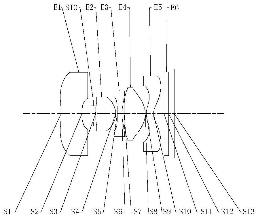
[0073] figure 1 Shown is a schematic structural view of the optical imaging lens according to the first embodiment of the present invention, as figure 1 As shown, the imaging lens assembly includes sequentially from the object side to the image side, the stop STO, the first lens E1, the second lens E2, the third lens E3, the fourth lens E4, the fifth lens E5, the filter E6 and Imaging surface S13.
[0074] Wherein, the first lens E1 has negative refractive power, its object side S1 is concave, and the image side S2 is concave; the second lens E2 has positive refractive power, its object side S3 is convex, and the image side S4 is convex; the third lens E3 has negative refractive power, its object side S5 is convex, and its image side S6 is concave; the fourth lens E4 has positive refractive power, its object side S7 is concave, and its image side S8 is convex; the fifth lens E5 has negative optical focus degree, the object side S9 is convex, and the image side S10 is concave...
Embodiment 2
[0101] Figure 6 Shown is a schematic structural view of the optical imaging lens of the second embodiment of the present application, as Figure 6 As shown, the imaging lens assembly includes sequentially from the object side to the image side, the stop STO, the first lens E1, the second lens E2, the third lens E3, the fourth lens E4, the fifth lens E5, the filter E6 and Imaging surface S13.
[0102] Wherein, the first lens E1 has negative refractive power, its object side S1 is concave, and the image side S2 is concave; the second lens E2 has positive refractive power, its object side S3 is convex, and the image side S4 is convex; the third lens E3 has negative refractive power, its object side S5 is convex, and its image side S6 is concave; the fourth lens E4 has positive refractive power, its object side S7 is concave, and its image side S8 is convex; the fifth lens E5 has negative optical focus degree, the object side S9 is convex, and the image side S10 is concave. Th...
Embodiment 3
[0115] Figure 11 Shown is a schematic structural view of the optical imaging lens according to the third embodiment of the present application, as Figure 11 As shown, the imaging lens assembly includes sequentially from the object side to the image side, the stop STO, the first lens E1, the second lens E2, the third lens E3, the fourth lens E4, the fifth lens E5, the filter E6 and Imaging surface S13.
[0116] Wherein, the first lens E1 has negative refractive power, its object side S1 is concave, and the image side S2 is concave; the second lens E2 has positive refractive power, its object side S3 is convex, and the image side S4 is convex; the third lens E3 has negative refractive power, its object side S5 is convex, and its image side S6 is concave; the fourth lens E4 has positive refractive power, its object side S7 is concave, and its image side S8 is convex; the fifth lens E5 has negative optical focus degree, the object side S9 is convex, and the image side S10 is c...
PUM
 Abstract
Description
Claims
Application Information