
Imaging system of off-axis optical field

A light field imaging and imaging system technology, applied in the optical field, can solve the problems of reduced imaging quality of optical lenses, complicated preparation and high cost, and achieve the effect of balancing the scene switching problem, low preparation cost and low energy loss

Pending Publication Date: 2018-05-18
北京崭珀科技有限公司
View PDF1 Cites 2 Cited by
  • Summary
  • Abstract
  • Description
  • Claims
  • Application Information

AI Technical Summary

Problems solved by technology

[0004] 1. The optical distortion is large, and the optical lens will have different degrees of distortion due to the influence of its structure
[0005] 2. Dispersion, because the refractive index of different wavelengths of light in the same medium is different, it will cause dispersion problems
[0006] 3. The secondary spectrum, for a long focal length lens, the focal length is longer, the secondary spectrum has a large chromatic aberration, and the clarity and resolution of the photo will be reduced
[0007] 4. Energy loss, because the energy will be lost after the light passes through different media, and the final image quality will be reduced
[0008] 5. The preparation is complicated. In order to avoid some problems, the optical lens is generally composed of multiple lenses, so the preparation process is complicated
[0009] 6. The cost is high, because the small error of the optical lens will lead to the decline of the imaging quality, the cost of the current optical lens is generally high

Method used


Image

  • Imaging system of off-axis optical field

Examples


Embodiment Construction

[0033] In order to explain the overall concept of the present application more clearly, the following detailed description will be given by way of examples in combination with the accompanying drawings. It should be noted that in this article, relative terms such as "first" and "second" are only used to distinguish one entity or operation from another entity or operation, and do not necessarily require or imply these There is this actual relationship or order between entities or operations. Furthermore, the terms "comprises", "comprising", or any other similar description are intended to cover a non-exclusive inclusion such that a series of processes, methods, articles, or devices includes not only those elements, but also includes elements not expressly listed. other elements of, or also elements inherent in, such a process, method, article or apparatus. An element defined by a statement "comprising a", etc. does not exclude, without further limitations, from including said ...


PUM


Abstract

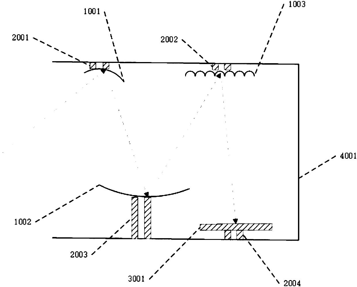
The invention relates to an imaging system of an off-axis optical field. The imaging system of the off-axis optical field sequentially comprises an off-axis reflection subsystem, a micro-reflection mirror array and an optical sensing device along the imaging optical path, wherein the off-axis reflection subsystem comprises at least one optical device containing a reflection curved surface, and atleast one adjusting mechanism which is matched with the corresponding optical device with the reflection curved surface; the imaging optical path passes through the optical device with the reflectioncurved surface; each adjusting mechanism is used for adjusting the optical device with the reflection curved surface.

Description

technical field [0001] The present application relates to the field of optics, in particular to an off-axis light field imaging system. Background technique [0002] The definition of light field can be traced back to the definition given by Faraday in 1846, which refers to the amount of light passing through each point in each direction, expressed by a seven-dimensional function, P(Vx,Vy,Vz ,θ, λ,t). Based on this definition, later scientists simplified it into the 5D plenoptic function for us, using the function P(Vx,Vy,Vz,θ, ), however, the five-dimensional function is still difficult to reconstruct, and finally it is simplified to the four-dimensional light field theory again, expressed by the function P(u,v,x,y), and the full-light field camera we see today is based on this theory from the research results. This technology is used in cameras, bringing about a revolution in camera technology. [0003] Light field imaging systems have been recorded in the prior art...

Claims


Application Information

Patent Timeline
Patent Type & Authority Applications(China)
IPC IPC(8): G02B17/06G02B26/08G02B7/182
CPCG02B7/1821G02B17/06G02B26/0833
Inventor 胡晓明
Owner 北京崭珀科技有限公司
Learn More