Optical filter, optical filter module, spectrometric measurement apparatus, and optical apparatus

a technology of optical filters and optical films, applied in the direction of optical radiation measurement, instruments, spectrometry/spectrophotometry/monochromators, etc., can solve the problems of increasing the voltage for driving the movable portion, complicated structure of optical films for providing the necessary band of variable wavelength filters, and complicated structure of optical films, etc., to achieve wide wavelength range, simplify configuration, and the effect of reducing the effect of voltag

Inactive Publication Date: 2012-01-12
SEIKO EPSON CORP
View PDF3 Cites 14 Cited by
  • Summary
  • Abstract
  • Description
  • Claims
  • Application Information

AI Technical Summary

Benefits of technology

[0044]According to this aspect of the invention, a spectrometric measurement apparatus having a simplified configuration, being compact and lightweight, with an ability to cover a wide wavelength range, excellent usability, and other advantages can be provided. The signal processor performs predetermined signal processing based on signals (received light signals) provided from the light receiving devices, for example, to measure a spectrophotometric distribution of a sample. Measuring a spectrophotometric distribution allows, for example, measurement of the color of the sample and analysis of components contained in the sample. It is noted that the accuracy in spectrometric measurement can be improved by performing noise removal correction on the signals provided from the light receiving devices. Further, the noise, which results from a wide full width at half maximum transmittance of each filter and other factors, is a received light component corresponding to an unwanted band and superimposed on a received light signal provided from each filter.
[0045](12) According to a yet further aspect of the invention, there is provided an optical apparatus including any of the optical filters described above. According to this aspect of the invention, the optical apparatus (a variety of sensors and optical communication-related apparatus, for example) having a simplified configuration, being compact and lightweight, with an ability to cover a wide wavelength range, and excellent usability is provided.

Problems solved by technology

The moving of the movable portion disadvantageously increases the moving range of the movable portion of the variable wavelength filter and hence increases the voltage for driving the movable portion.
Another problem with a wide wavelength range of the transmitted light is that the structure of the optical films for providing a necessary band of the variable wavelength filter is complicated.
In other words, the optical films need to be designed so that the entire desired wavelength band can be covered, resulting in a complicated structure of the optical films.
When the structure of the optical films is complicated, it increases a burden related to manufacturing processes and decreases the intensity of the transmitted light.
Other inconveniences also tend to occur.
In this case, the fact described above may cause the first wavelength band on the shorter wavelength side to be narrower than the second wavelength band so that it is difficult to allocate four spectral bands to the first wavelength band (that is, may make it difficult to provide four measurement points).
In this case, the burden of manufacturing the optical films increases.
Further, the noise, which results from a wide full width at half maximum transmittance of each filter and other factors, is a received light component corresponding to an unwanted band and superimposed on a received light signal provided from each filter.

Method used


Image

  • Optical filter, optical filter module, spectrometric measurement apparatus, and optical apparatus
  • Optical filter, optical filter module, spectrometric measurement apparatus, and optical apparatus
  • Optical filter, optical filter module, spectrometric measurement apparatus, and optical apparatus

Examples


first embodiment

[0063]In a first embodiment, an example of a structure and action of an optical filter (including a plurality of variable wavelength bandpass filters) will be described with reference to an optical apparatus (a spectrometric measurement apparatus in the following description) including the optical filter. Examples of the spectrometric measurement apparatus may include a colorimeter, a spectrometric analysis apparatus, and an optical spectrum analyzer.

Example of Overall Configuration of Spectrometric Measurement Apparatus and Example of Configuration of Optical Filter

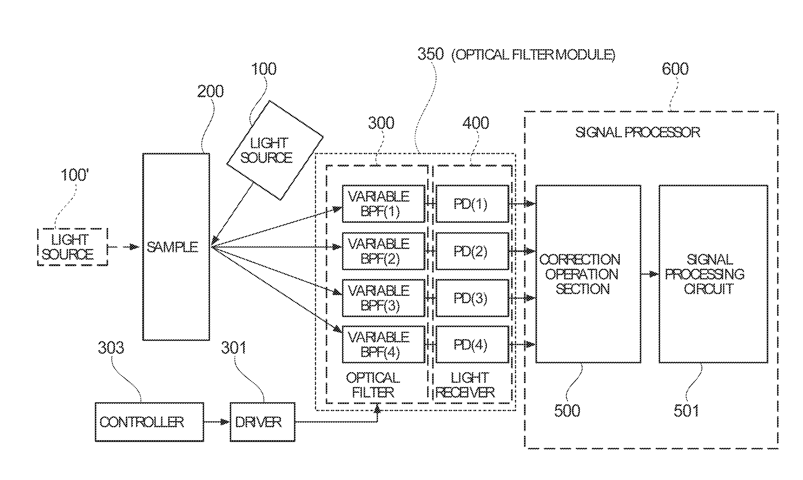
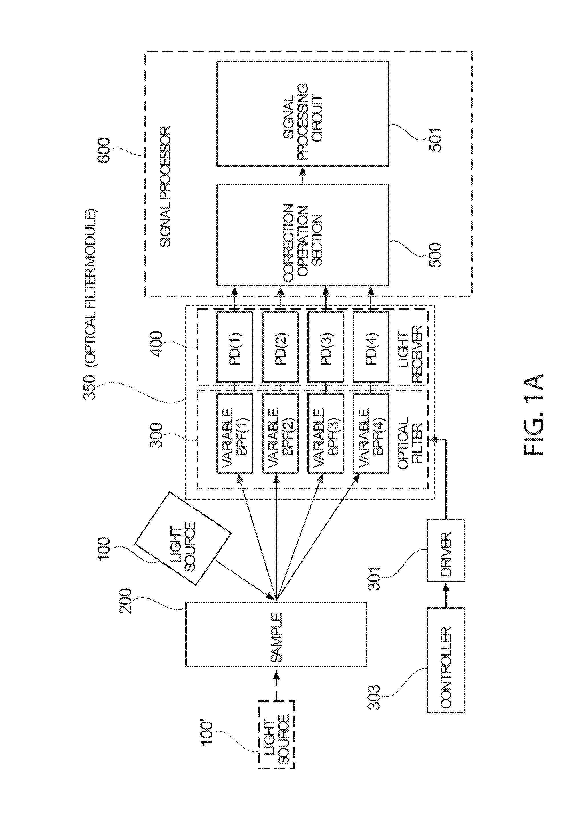
[0064]FIG. 1A shows an example of the overall configuration of a spectrometric measurement apparatus, and FIG. 1B shows an example of the configuration of an optical filter. For example, a light source 100 is used when the color of a sample 200 is measured, and a light source 100′ is used when the sample 200 is analyzed spectrometrically.

[0065]As shown in FIG. 1A, the spectrometric measurement apparatus includes the ligh...

second embodiment

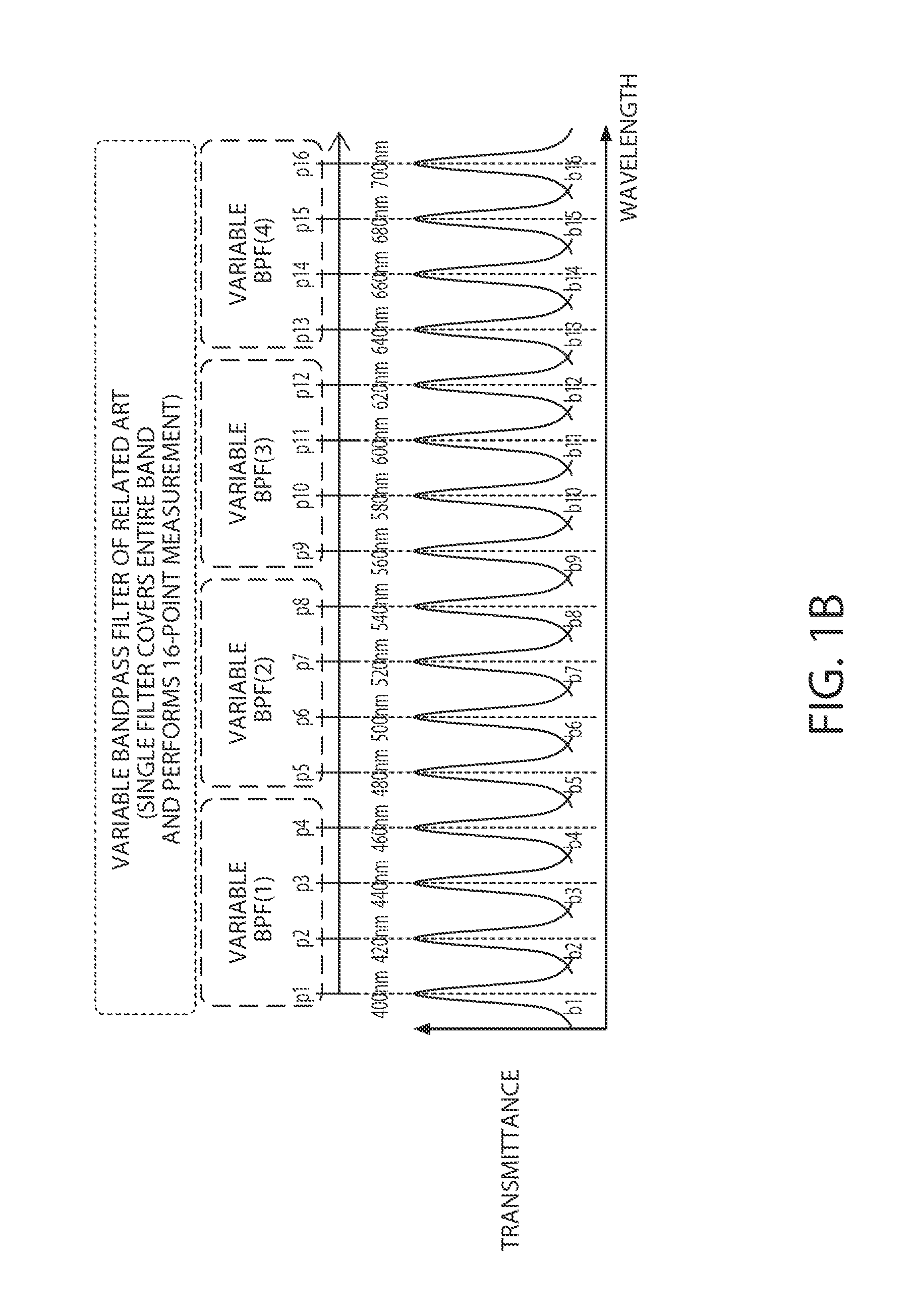
[0110]In the embodiment described above, the first wavelength band (400 to 460 nm) and the adjacent second wavelength band (480 to 540 nm) have the same bandwidth (see FIG. 1B). In contrast, in a second embodiment, the bandwidth of the first wavelength band and that of the adjacent second wavelength band are set to be different from each other. When the second wavelength band is located on a longer wavelength side of the first wavelength band, the bandwidth of the second wavelength band is set to be wider than that of the first wavelength band. The reason for this is a reflection of the fact that it is difficult for a bandpass filter to provide a wide wavelength band when it is located in a short wavelength area within the entire wavelength range.

[0111]For example, when the optical films used in the first variable wavelength bandpass filter that extracts light of the first wavelength band and the second variable wavelength bandpass filter that extracts light of the second wavelength...

third embodiment

[0137]In a third embodiment, a holding period for each spectral band in each variable wavelength bandpass filter is of interest. For example, when the spectral band of a first variable wavelength bandpass filter is changed m times, let Δtm be a holding period for each of the m spectral bands, and when the spectral band of a second variable wavelength bandpass filter is changed n times (n>m), let Δtn be a holding period for each of the n spectral bands. In this case, Δtm and Δtn are set to satisfy Δtm>Δtn.

[0138]For example, assume a case where variable gap etalon filters are used as the first and second variable wavelength bandpass filters and the total travels of the movable substrates in the variable wavelength bandpass filters (total amounts of change in the gap size), which typically differ from each other between filters having respective wavelength bands, are the same. For example, when the gap between each of the movable substrates and its counterpart is changed by G in total,...


PUM


Abstract

An optical filter includes: a first variable wavelength bandpass filter that can extract light of a first wavelength band (400 to 460 nm), the first wavelength band having a first spectral band having a central wavelength equal to a first wavelength in the first wavelength band and a second spectral band having a central wavelength equal to a second wavelength in the first wavelength band; and a second variable wavelength bandpass filter that can extract light of a second wavelength band (480 to 540 nm) adjacent to the first wavelength band, the second wavelength band having a third spectral band having a central wavelength equal to a third wavelength in the second wavelength band and a fourth spectral band having a central wavelength equal to a fourth wavelength in the second wavelength band.

Description

[0001]This application claims priority to Japanese Patent Application No. 2010-154158 filed Jul. 6, 2010 which is hereby expressly incorporated by reference herein in its entirety.BACKGROUND[0002]1. Technical Field[0003]The present invention relates to an optical filter, an optical filter module, a spectrometric measurement apparatus, an optical apparatus, and other apparatuses.[0004]2. Related Art[0005]An interference filter has been used in a spectrometric measurement apparatus and other optical apparatuses. A known aspect of the interference filter selects a wavelength of light that passes therethrough (Fabry-Perot etalon interference filter) (see JP-A-11-142752, for example). A transmissive variable wavelength interference filter described in JP-A-11-142752 (hereinafter sometimes referred to as a variable gap etalon filter or simply referred to as a variable gap etalon), which can select the wavelength of light passing therethrough, includes a pair of substrates held in parallel...

Claims


Application Information

Patent Timeline
Patent Type & Authority Applications(United States)
IPC IPC(8): G01J3/28G02B26/00
CPCG02B5/284G01J3/26G02B26/001G02B5/288G01J3/02G02B5/28
Inventor MATSUSHITA, TOMONORIURUSHIDANI, TATSUO
Owner SEIKO EPSON CORP
Why Eureka
Try Eureka