
Wavelength-selective diffraction element and optical head device incorporating the same

a diffraction element and wavelength-selective technology, applied in the field of wavelength-selective diffraction elements and optical head devices incorporating the same, can solve the problem of restricting the degree of freedom in selecting a diffraction efficiency

Inactive Publication Date: 2008-12-25
ASAHI GLASS CO LTD
View PDF4 Cites 16 Cited by
  • Summary
  • Abstract
  • Description
  • Claims
  • Application Information

AI Technical Summary

Benefits of technology

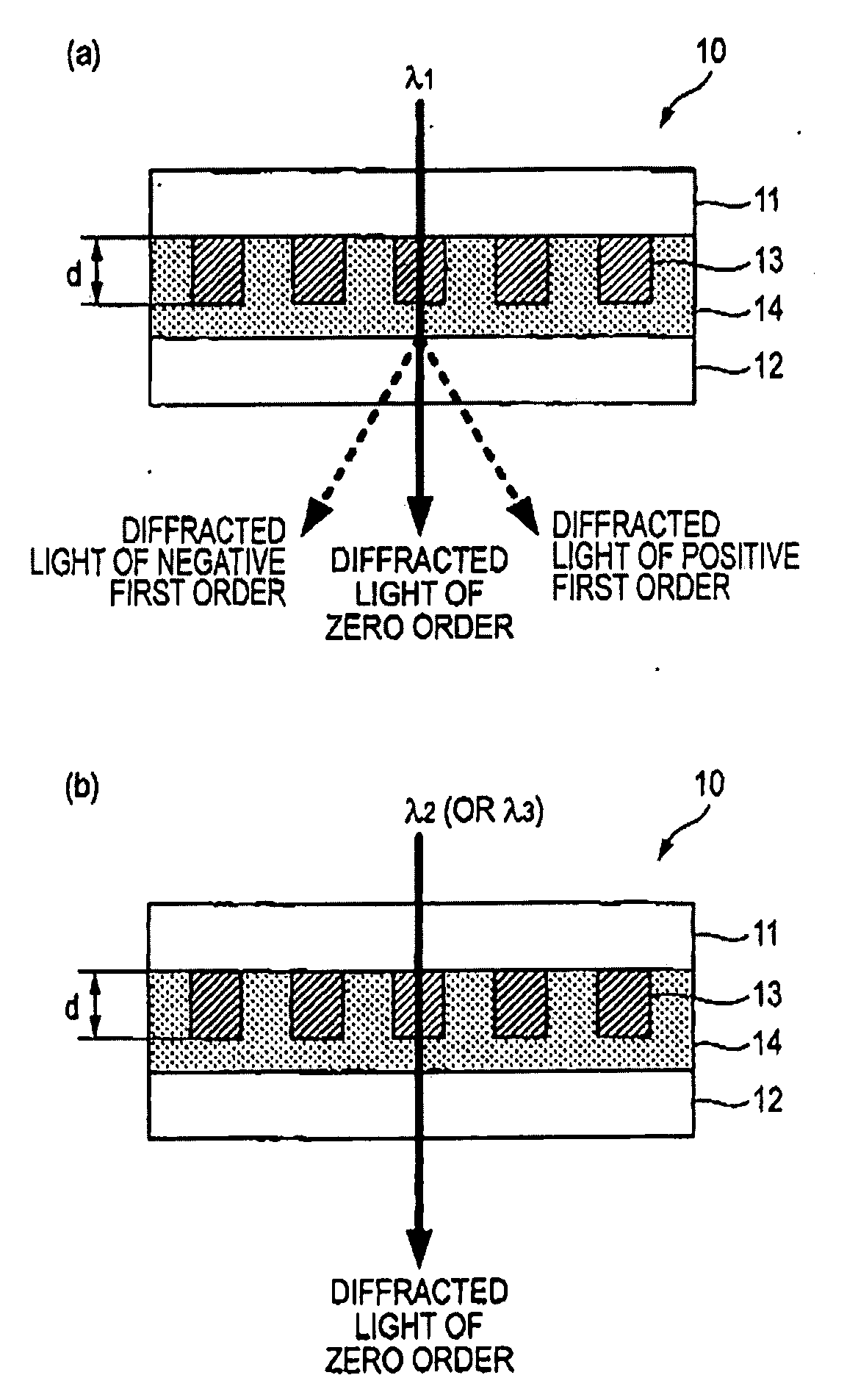
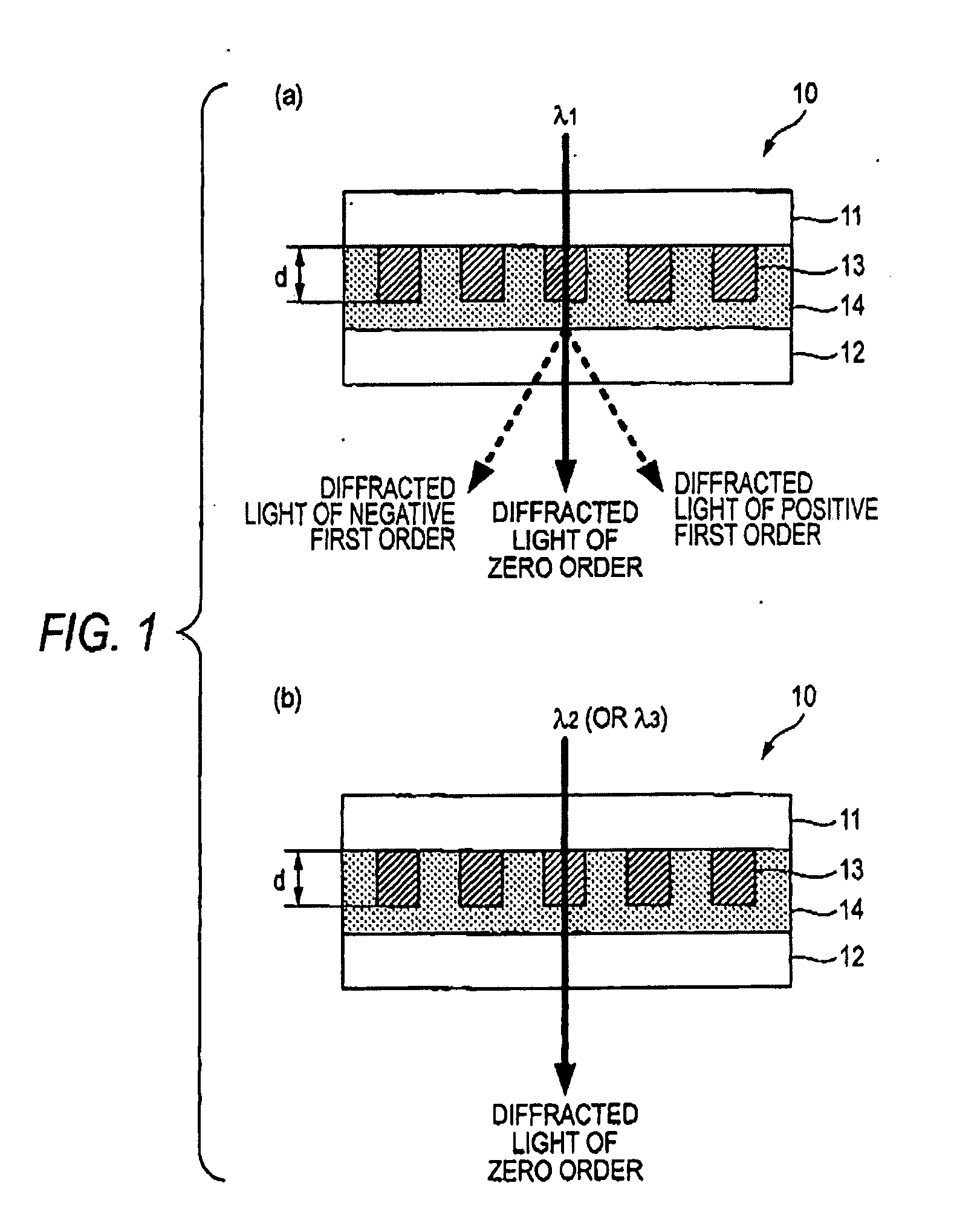
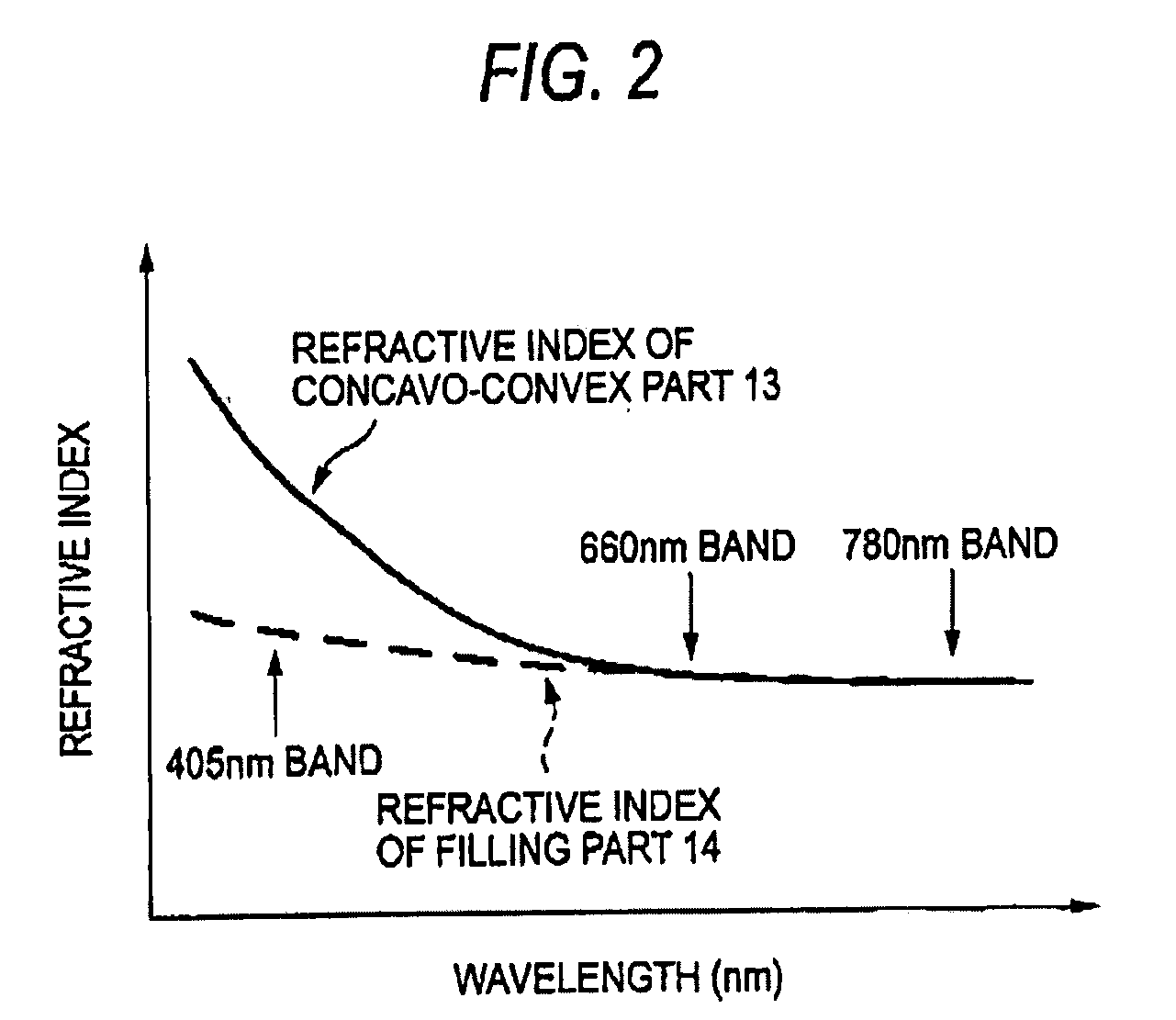
The present invention provides a wavelength-selective diffraction element and an optical head device that can selectively diffract light of a wider range of wavelengths than conventional elements. The element uses a transparent substrate and a concavo-convex part and a filling part, which have no absorbance with respect to the incident light and have an identical refractive index to light of a first wavelength. The refractive indices of the materials are different for light of a second wavelength, allowing the element to selectively diffract the light of a wavelength range wider than conventional elements. This makes it possible to selectively diffract the light of a next generation DVD, which uses blue laser light of a 405 nm band.

Problems solved by technology

However, in the wavelength-selective diffraction element disclosed in the Patent Document 1, since a condition that the length of the optical path difference is set, for the incident light of the first wavelength, to the value the integer times as large as the first wavelength restricts a degree of freedom in a design for the incident light of the second wavelength, a problem arises that a degree of freedom in selecting a diffraction efficiency is restricted.

Method used


Image

  • Wavelength-selective diffraction element and optical head device incorporating the same
  • Wavelength-selective diffraction element and optical head device incorporating the same
  • Wavelength-selective diffraction element and optical head device incorporating the same

Examples


first embodiment

[0075]Initially, the structure of a wavelength-selective diffraction element according to a first embodiment of the present invention will be described. In the wavelength-selective diffraction element of this embodiment, examples that the wavelength-selective diffraction element according to this embodiment is applied to the standards of a BD (Blu-ray Disc) or an HD DVD (High Definition DVD) and a DVD and a CD will be explained. In the below description, the BD or the HD DVD is referred to simply as a “BD or the like”. Further, wavelengths of light used for reading and writing data on the BD or the like, the DVD and the CD are respectively designated by λ1, λ2, and λ3. Here, the light of the wavelengths λ1, λ2 and λ3 respectively indicate the light of the wavelengths of a 405 nm band, a 660 nm band and a 780 nm band. The wavelengths of the 405 nm band, the 660 nm band and the 780 nm band respectively mean wavelength ranges of 405±15 nm, 660±15 nm and 780±20 nm.

[0076]As shown in FIG....

example 1

[0091]Initially, on the transparent substrate 11 made of the glass substrate, a film of a first photo-polymerizing polymer is formed under a state of a monomer by a spin coat method. Then, the formed monomer is polymerized by applying a ultraviolet ray to have a photo-polymer and a polymer film having the thickness of 25 μm is formed. Further, the polymer film is formed in the configuration of a grating of a pitch of 12 μm by a dry etching method to obtain the concavo-convex part 13.

[0092]Subsequently, the grating-shaped concavo-convex part 13 are filled with a second photo-polymerizing polymer under the state of a monomer, and then, the transparent substrate 12 made of the glass substrate is laminated thereon. Then, the filled monomer is polymerized by applying the ultraviolet ray to obtain the wavelength-selective diffraction element 10.

[0093]The above-described first and second photo-polymerizing polymers are any of the polymer materials such as the polyester material, the polyet...

second embodiment

[0117]Initially, the structure of a wavelength-selective diffraction element according to a second embodiment of the present invention will be described. It is exemplified that the wavelength-selective diffraction element of this embodiment is applied to the standards of a BD or the like, a DVD and a CD like the wavelength-selective diffraction element 10 according to the first embodiment of the present invention (see FIG. 1) and duplicated explanations will be omitted.

[0118]As shown in FIG. 5, the wavelength-selective diffraction element 20 according to this embodiment comprises a pair of transparent substrates 21 and 22, a concavo-convex part 23 formed on the transparent substrate 21 in which concave portions and convex portions are cyclically extended in one direction, and a filling part 24 provided so as to fill at least the concave portions of the concavo-convex part 23.

[0119]In FIG. 5, (a) shows a state that the light of a wavelength λ1 is incident on and transmitted by the wa...


PUM

PropertyMeasurementUnit
wavelengthaaaaaaaaaa
light wavelengthaaaaaaaaaa

Abstract

The present invention provides a wavelength-selective diffraction element, configured such that light having a plurality of wavelengths are incident thereon as incident light, which is provided with: a transparent substrate; a concavo-convex part, formed on the transparent substrate such that concave portions and convex portions are cyclically extended in one direction, and comprised of a first material which is optically isotropic; and a filling part, filling at least the concave portions and comprised of a second material which is optically isotropic. The first material and the second material have no absorbance with respect to the wavelengths of the incident light. The first material and the second material have an identical refractive index with respect to light having a first wavelength which is at least one of the wavelengths of the incident light. The first material and the second material have different refractive indices with respect to light having a second wavelength which is at least one of the wavelengths of the incident light and different from the first wavelength.

Description

TECHNICAL FIELD[0001]The present invention relates to a wavelength-selective diffraction element that can selectively diffract light of a plurality of wavelengths different from one another, and to an optical head device incorporating such a wavelength-selective diffraction element.BACKGROUND ART[0002]A conventional wavelength-selective diffraction element comprises a glass substrate and a dielectric material cyclically formed on the glass substrate. For incident light having a first wavelength, the length of an optical path difference between a part having the dielectric material formed on the glass substrate and a part having no dielectric material is set to a value integer times as large as the first wavelength to transmit the incident light having the first wavelength. For incident light having a second wavelength, the above-described length of the optical path difference is set to a value non-integer times as large as the second wavelength to diffract the incident light having ...

Claims


Application Information

Patent Timeline
Patent Type & Authority Applications(United States)
IPC IPC(8): G02B5/18G11B7/135
CPCG02B5/1871G11B7/1353G02B5/18
Inventor KOYANAGI, ATSUSHISATO, HIROMASATAO, YUKIHIROMIYASAKA, KOJI
Owner ASAHI GLASS CO LTD
Learn More