
Method for producing ultrathin quartz crystal phase retardation plate

A technology of phase retardation plates and quartz crystals, applied in stone processing equipment, surface polishing machine tools, fine working devices, etc., can solve problems such as unstable product quality, affecting industrial development, and low yield, and achieve anti-light damage High threshold, attractive market prospects, and good mechanical properties

Inactive Publication Date: 2012-06-20
昆山明本光电有限公司
View PDF6 Cites 15 Cited by
  • Summary
  • Abstract
  • Description
  • Claims
  • Application Information

AI Technical Summary

Problems solved by technology

[0004] Nowadays, high-power lasers are applied in smaller and smaller areas or spot diameters to meet the more stringent performance requirements of consumer electronics, which also increases the demand for ultra-thin quartz crystal phase retardation plates, and due to the single The thickness of an ultra-thin quartz crystal phase retardation plate (true zero-order wave plate) is too thin. The traditional process uses double-sided polishing technology to directly polish the product, which is easily broken, resulting in low yield and unstable product quality. Serious Influenced the development of related industries

Method used


Image

  • Method for producing ultrathin quartz crystal phase retardation plate
  • Method for producing ultrathin quartz crystal phase retardation plate

Examples


Embodiment 1

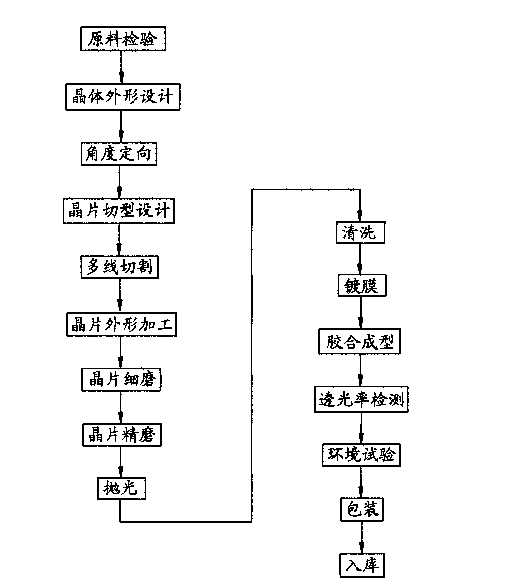
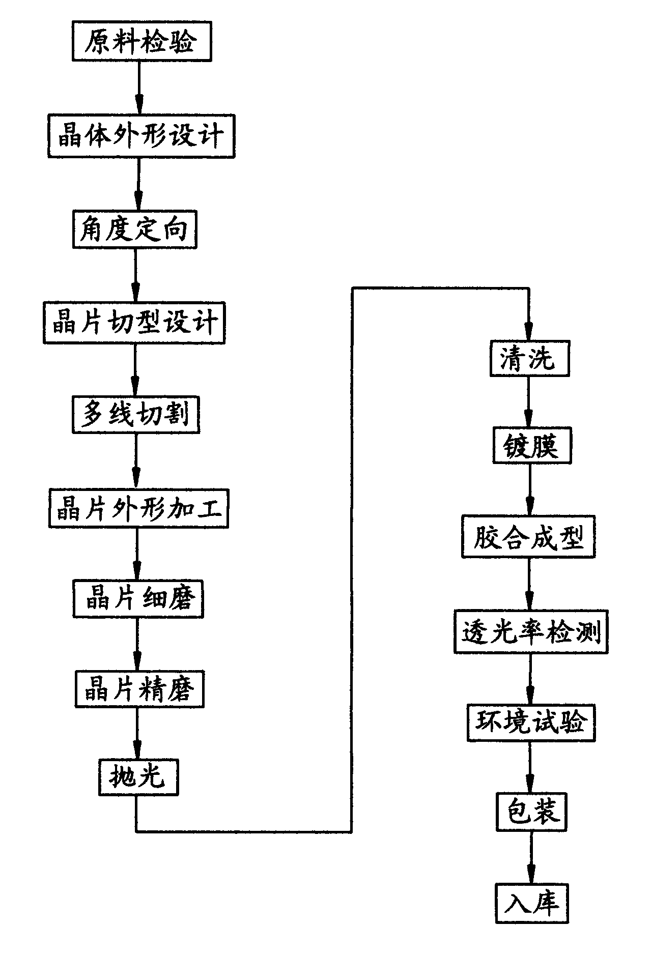
[0018] Such as figure 1 As shown, the production method of the ultra-thin quartz crystal phase retardation plate in this embodiment sequentially includes raw material inspection, crystal shape design, angle orientation, wafer cutting design, multi-wire cutting, wafer shape processing, wafer fine grinding, wafer fine grinding, Polishing, cleaning, coating, gluing, light transmittance detection, environmental testing, packaging, and warehousing processes; in the polishing process, the wafer to be polished is first glued to the substrate, and then the polishing operation is performed; in the cleaning process , the substrate is first separated from the wafer, and then the wafer is cleaned.

[0019] Among them, the standard indicators for raw material inspection are: Z-axis direction size: 30-50 mm; inclusion number: Ia standard; corrosion tunnel density in the crystal seed: 2 ;Q value: ≥2.6*10 6 ; Optical uniformity: Δn≤5*10 -6 .

[0020] In the above-mentioned polishing proces...


PUM


Abstract

The invention provides a method for producing an ultrathin quartz crystal phase retardation plate with high yield and stable quality. The method sequentially comprises the following working procedures of checking raw materials, designing the shape of a crystal, orientating an angle, designing a cutting form of a crystal plate, cutting a plurality of lines, processing the shape of the crystal plate, and grinding, polishing, washing, plating, gluing, forming, detecting and packaging the crystal plate, and putting into storage. The key point is that: in the polishing working procedure, the crystal plate to be polished is glued on a substrate, and then is polished; and in the washing working procedure, the substrate is separated from the crystal plate, and then the crystal plate is washed. The single quartz crystal to be polished is glued on the substrate, so that the mechanical strength of the single quartz crystal to be polished is improved; and then the single quartz crystal to be polished is polished, so that the crystal plate has extremely high parallelism, high transmittance, high light loss resistance threshold value and high mechanical performance, is particularly stable in use occasions with a large temperature difference range, has a wide wavelength range, permits large-angle incidence (about 20 degrees), and can be applied to the use occasions with high loss threshold value (more than 1 GW / cm<2>).

Description

technical field [0001] The invention belongs to the technical field of electronic manufacturing, and in particular relates to a production method of an ultra-thin quartz crystal phase retardation plate. Background technique [0002] As a laser polarizing device, quartz crystal phase retardation plate (wave plate) can be used in scientific research and military lasers, medical lasers, instruments, lasers for sensors, photoelectric output and input equipment, laser entertainment and displays, optical communications in the telecommunications industry, etc. The range of applications is very wide. [0003] At present, quartz crystal phase retardation plates are mainly provided by manufacturers in the United States and Japan, such as THORLABS, EPSON, KYOCERA, etc. There are also manufacturers in South Korea and Taiwan that have started to develop and produce this product a few years ago, but they are all in the stage of small-scale production. Since there is no quartz crystal pro...

Claims


Application Information

Patent Timeline
Patent Type & Authority Applications(China)
IPC IPC(8): G02B5/30B24B29/02B28D5/00
Inventor 冷志红
Owner 昆山明本光电有限公司
Learn More