Supercharge Your Innovation With Domain-Expert AI Agents!

Optical transceiver, method for controlling the optical transceiver and non-transitory computer readable medium embodying instructions for controlling a device

Inactive Publication Date: 2013-09-19
NEC CORP
View PDF3 Cites 18 Cited by
  • Summary
  • Abstract
  • Description
  • Claims
  • Application Information

AI Technical Summary

Benefits of technology

The patent text describes a way to adjust transmitter signals without using an external system and without needing a personal computer for adjustment. This makes it easy to use the adjustment program even when the measurement environment changes. The technical effect of this is improved efficiency and flexibility in adjusting transmitter signals.

Problems solved by technology

Further, exemplary embodiments are not required to achieve the objectives described above, and an exemplary embodiment may not achieve any of the objectives described above.

Method used


Image

  • Optical transceiver, method for controlling the optical transceiver and non-transitory computer readable medium embodying instructions for controlling a device
  • Optical transceiver, method for controlling the optical transceiver and non-transitory computer readable medium embodying instructions for controlling a device
  • Optical transceiver, method for controlling the optical transceiver and non-transitory computer readable medium embodying instructions for controlling a device

Examples


second embodiment

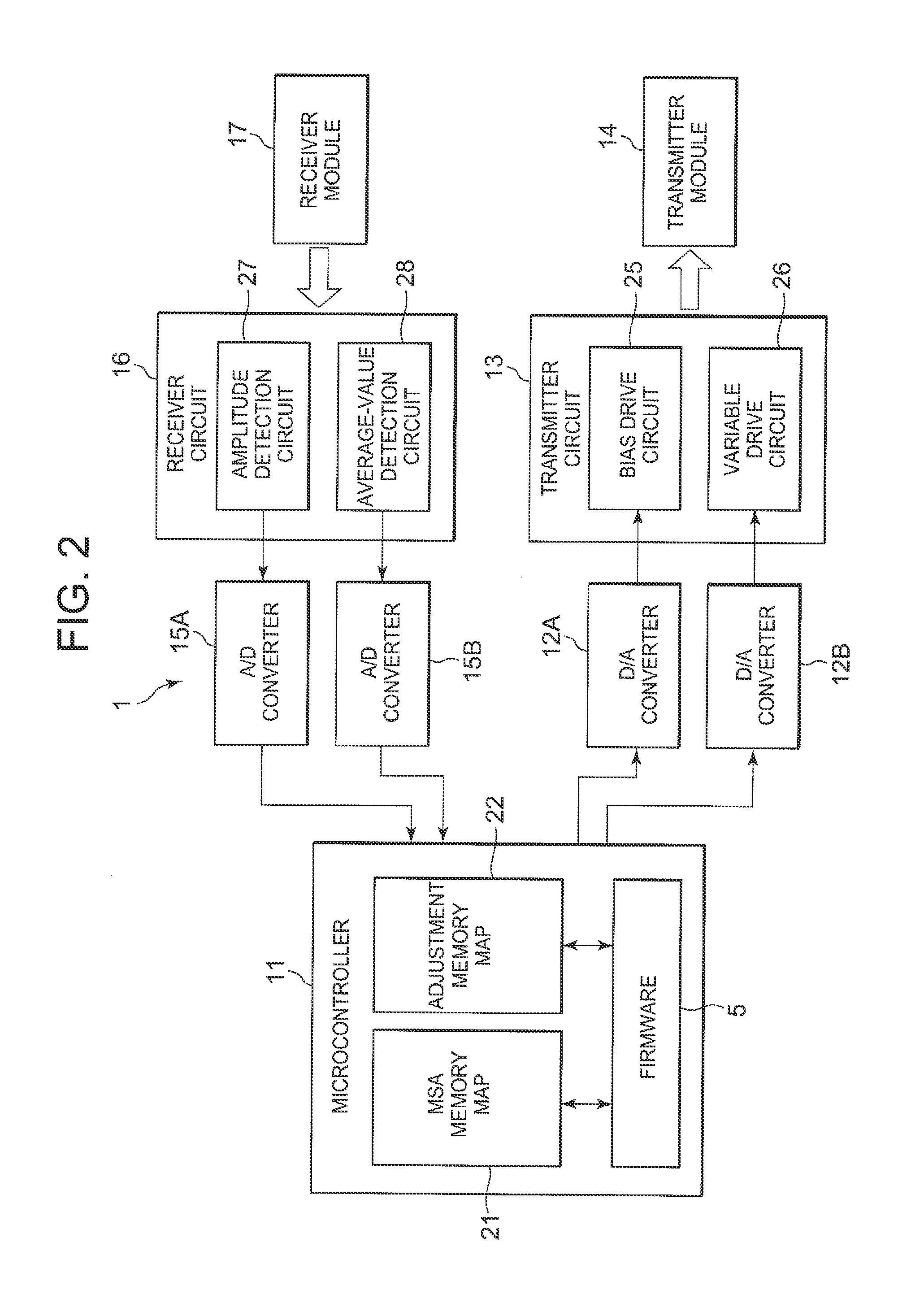
[0040]FIG. 6 illustrates the hardware configuration of an optical transceiver 41 according to the second exemplary embodiment. In the optical transceiver 41, the A / D converters 15A, 15B and D / A converters 12A, 12B are implemented as functions in the microcontroller 11.

third embodiment

[0041]FIG. 7 illustrates the hardware configuration of an optical transceiver 51 according to the third exemplary embodiment. In the optical transceiver 51, functions 25, 26 on the transmitter side and functions 27, 28 on the receiver side are implemented as functions of a single transmitter-receiver circuit 52.

fourth embodiment

[0042]FIG. 8 illustrates the hardware configuration of an optical transceiver 61 according to the fourth exemplary embodiment. In the optical transceiver 61, the A / D converters 15A, 15B, the D / A converters 12A, 12B, and transmitter and receiver functions 25, 26, 27, 28 are implemented by a single transmitter-receiver circuit 62.


PUM


Abstract

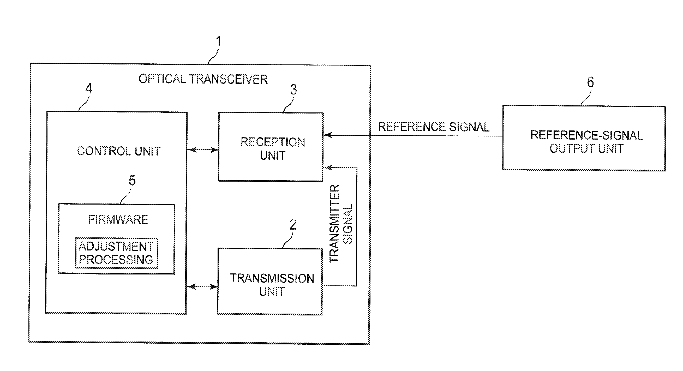
An optical transceiver includes a transmitter that transmits an optical signal, and a receiver that receives a reference signal. The receiver receives the optical signal transmitted by its own transmitter. A controller performs an adjustment of the optical signal, transmitted by the transmitter, based on the reference signal.

Description

BACKGROUND[0001]This document relates to an optical transceiver, and more particularly, to the adjustment of transmitter signals.RELATED ART[0002]Patent Literature 1 discloses an optical communication method and an optical transceiver. In the optical communication method according to Patent Literature 1, the optical transceiver acquires information about the transmission rate and data format of a baseband signal from an external interface. The optical transceiver also transmits to and receives from another optical transceiver a test signal at a transmission rate and in a transmission format that is set based on the information from the external interface. In addition, the optical transceiver sets a transmission rate and transmission format by comparing the transmission rate, set to transmit the test signal, with the transmission rate of the received test signal, and then transmits and receives information about data formats so as to select a data format. According to Patent Literatu...

Claims


Application Information

Patent Timeline
Patent Type & Authority Applications(United States)
IPC IPC(8): H04B10/40H04B10/07H04B17/00H04L69/40
CPCH04B10/40
Inventor ITO, YOTA
Owner NEC CORP
Features
  • R&D
  • Intellectual Property
  • Life Sciences
  • Materials
  • Tech Scout
  • Unparalleled Data Quality
  • Higher Quality Content
  • 60% Fewer Hallucinations
Learn More