Charged pigment particles for electrophoretic display

Inactive Publication Date: 2013-09-19
E INK CALIFORNIA
View PDF5 Cites 47 Cited by
  • Summary
  • Abstract
  • Description
  • Claims
  • Application Information

AI Technical Summary

Benefits of technology

[0009]The present invention is directed to a charged pigment particle useful for an electrophoretic fluid. The charged pigment particle comprises a core pigment particle, wherein the surface of the core pigment particle has be

Problems solved by technology

However, with the currently available techniques, aggregation of the charged pigment particles inevitably would occur, especial

Method used


Image

  • Charged pigment particles for electrophoretic display
  • Charged pigment particles for electrophoretic display
  • Charged pigment particles for electrophoretic display

Examples


Example

EXAMPLE 1

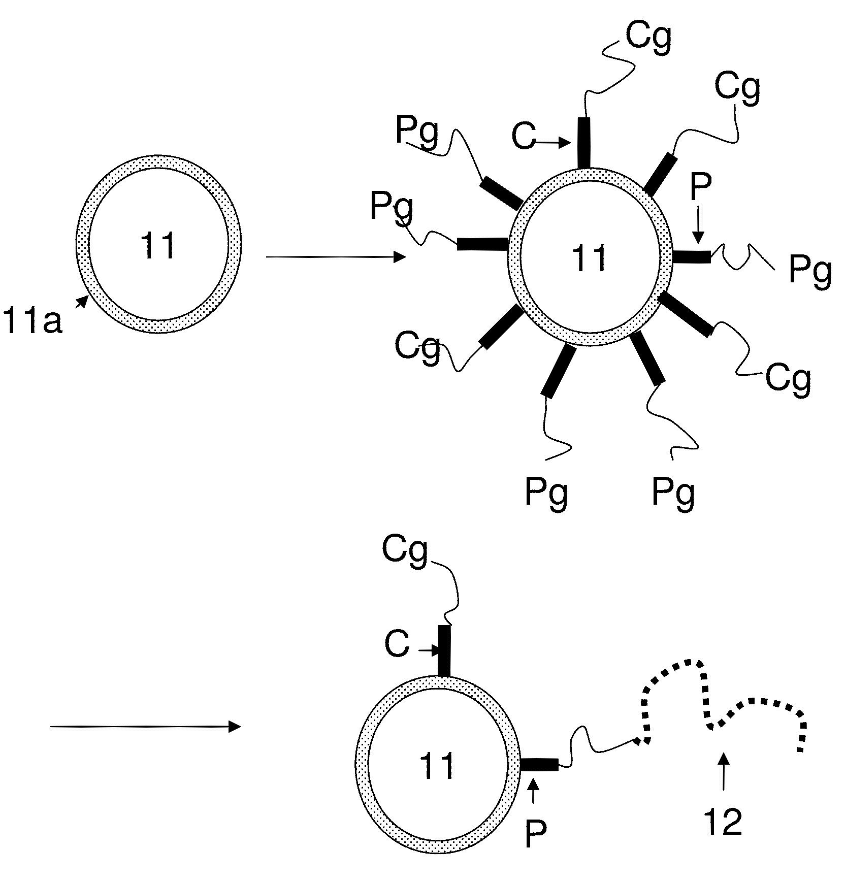
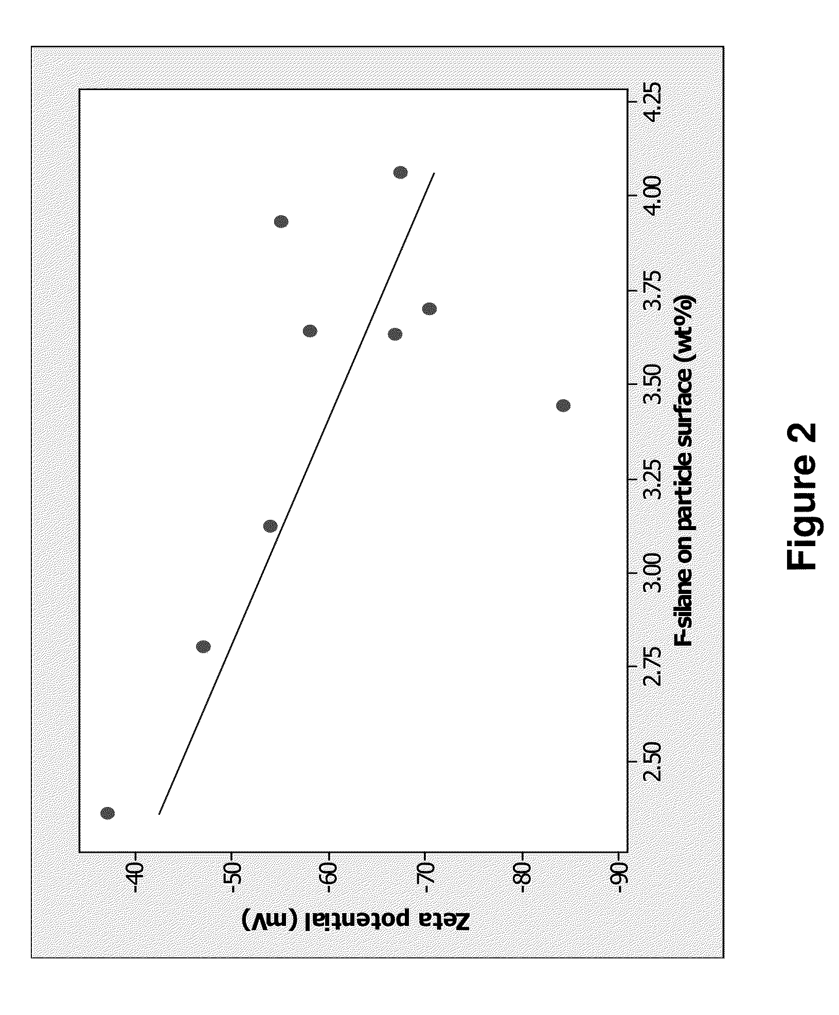
[0064]Experiments were carried out using the procedure as described in this application. The core pigment particles were TiO2 particles, (tridecafluoro-1,1,2,2-tetrahydrooctyl)trimethoxysilance was used as the coupling agent (C), and 3-(trimethoxysilyl)propyl methacrylate was used as the coupling agent (P). The final particles were dispersed in a dielectric solvent or solvent mixture with surfactants and / or charge controlling agents added. The Zeta potentials of the final particles were measured by ZetaPALS from BROOKHAVEN INSTRUMENTS CORPORATION.

[0065]As shown in FIG. 2, the charge level of the pigment particles can be controlled by adjusting the amount of the fluorinated silane, which is the coupling agent (C) on the particle surface. With more fluorinated silane on the particle surface, the pigment particles showed a higher negative charge.

[0066]While the present invention has been described with reference to the specific embodiments thereof, it should be understood by t...


PUM


Abstract

The present invention is directed to a charged pigment particles useful for the electrophoretic fluid. The present invention describes how the charge property of the charged pigment particle may be controlled. By adjusting the charge property of the charged pigment particles to a suitable level for an electrophoretic display system, a faster switching speed, a higher contrast ratio and better image bistability may be achieved.

Description

FIELD OF THE INVENTION[0001]The present invention is directed to charged pigment particles, an electrophoretic display fluid containing such charged pigment particles, and an electrophoretic display utilizing the electrophoretic fluid, and methods for their preparation.BACKGROUND OF THE INVENTION[0002]An electrophoretic display (EPD) is a non-emissive device based on the electrophoresis phenomenon influencing charged pigment particles dispersed in a dielectric solvent. An EPD typically comprises a pair of spaced-apart plate-like electrodes. At least one of the electrode plates, typically on the viewing side, is transparent. An electrophoretic fluid composed of a dielectric solvent with charged pigment particles dispersed therein is enclosed between the two electrode plates.[0003]An electrophoretic fluid may have one type of charged pigment particles dispersed in a solvent or solvent mixture of a contrasting color. In this case, when a voltage difference is imposed between the two el...

Claims


Application Information

Patent Timeline
IPC IPC(8): G03G17/00G02F1/167
CPCG02F1/167G02F2001/1678
Inventor WANG, MINGLAXTON, PETERDU, HUI
Owner E INK CALIFORNIA
Why Eureka
Try Eureka