Dual-stage high-contrast electronic image display

a display and electronic technology, applied in the field of electronic image displays, can solve the problems of slowing down the adoption of digital radiography among physicians, the contrast ratio of crt or lcd displays is still very low compared to the contrast ratio produced, and the performance of electronic displays cannot match the performance of traditional displays, etc., to achieve high contrast ratios, simple and inexpensive methods, and high contrast ratios

Inactive Publication Date: 2006-02-21
SAMSUNG ELECTRONICS CO LTD
View PDF12 Cites 105 Cited by
  • Summary
  • Abstract
  • Description
  • Claims
  • Application Information

AI Technical Summary

Benefits of technology

[0014]Some embodiments of the present invention provide an electronic display device capable of reproducing very high contrast ratios without objectionable parallax artifacts. These devices include at least two displays, wherein pixels of a first display are projected onto corresponding pixels of a second display. Some aspects of the invention provide simple and inexpensive methods for reproducing, on electronic displays, image data having very high contrast ratios. Still further specific embodiments of the invention provide radiologists and physicians a film-like electronic display with a gray scale range comparable to that of a conventional X-ray film viewed on a light box.

Problems solved by technology

However, there are some applications for which electronic displays still cannot match the performance of traditional displays.
Unfortunately, the contrast ratio of a CRT or LCD display is still very low compared to the contrast ratio produced by an X-ray film.
This is a very serious technical limitation, which is slowing the adoption of digital radiography among physicians.
Since CRTs and LCD panels cannot display the same number of gray scale levels as a conventional X-ray film, some of the diagnostic information in the image can be lost in the display process.
Even though this method does achieve the desired goal of increasing the overall contrast ratio, it introduces a number of undesirable artifacts caused by the parallax of light traversing both of the stacked LCD panels.
This parallax issue is more than a simple alignment issue between the two LCD panels; it is a fundamental problem caused by the fact that the two LCD panels cannot be infinitely close to each other and the backlight cannot be perfectly collimated.

Method used


Image

  • Dual-stage high-contrast electronic image display
  • Dual-stage high-contrast electronic image display
  • Dual-stage high-contrast electronic image display

Examples


first embodiment

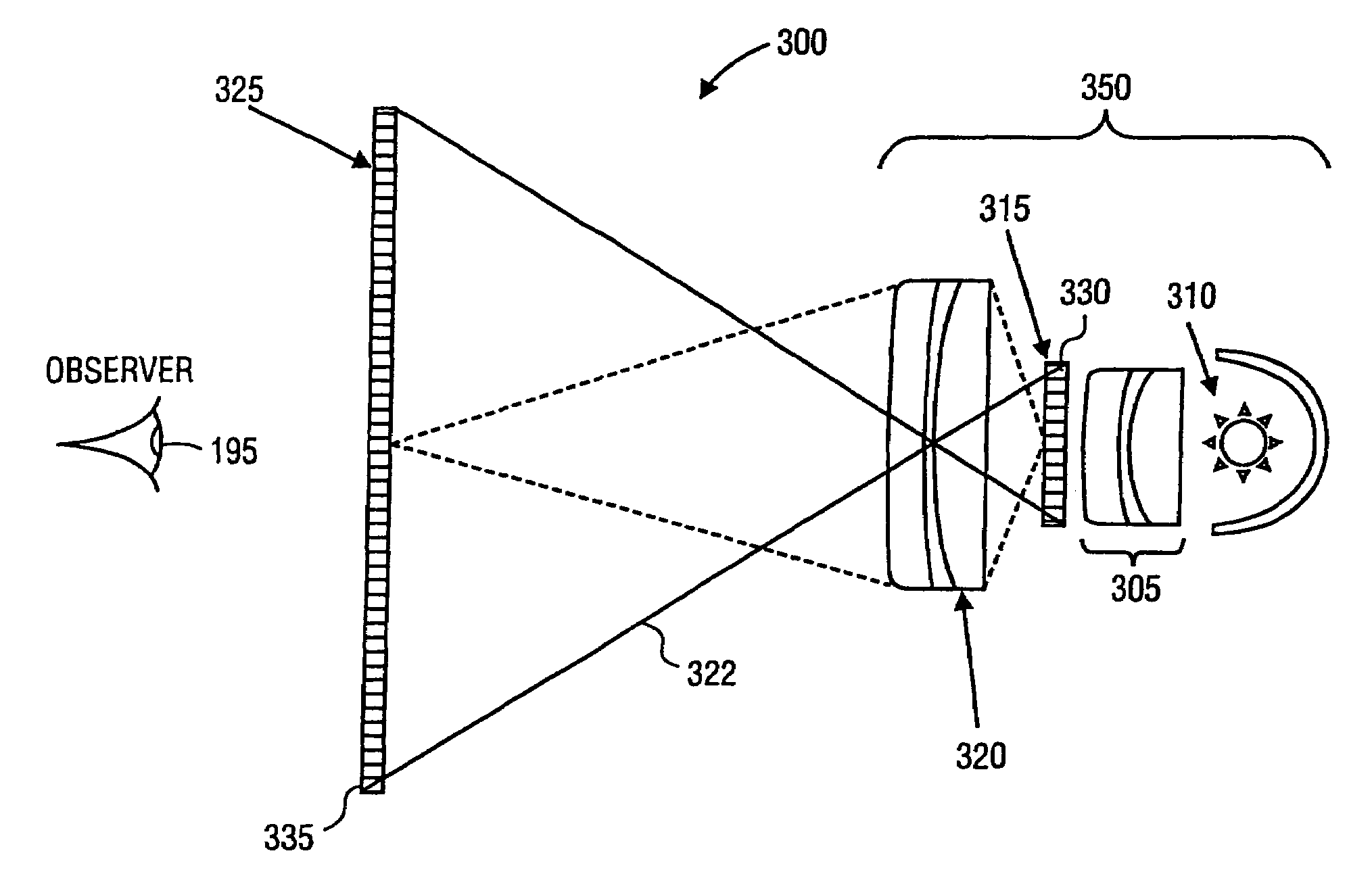
[0033] the invention comprises a dual display system in which two panels of identical spatial resolution are imaged one onto the other. The same electronic data (e.g. video signal or digital image file) are sent to both displays. Because of the multiplicative effect of cascaded displays, the contrast ratio of the combined display is a product of the contrast ratios of the front and rear panels. Rather than having two panels of the same size, some embodiments have a smaller panel (for example, a rear-projection LCD panel) that is imaged onto a larger panel through a projection lens. Preferably, both the smaller and the larger panels have the same number of total pixels.

[0034]Such an embodiment is illustrated in FIG. 3. Display device 300 includes lens assembly 305, which directs light from light source 310 to rear display 315. Projection lens assembly 320 focuses light from pixels of rear display 315 to corresponding pixels of front display 325. For example, light ray 322 emanates fr...

second embodiment

[0037] rear display 315 is not transmissive, but instead is reflective. The principle remains the same: the projected image from rear display 315 is focused onto front display 325 in lieu of the traditional backlight.

[0038]This second embodiment is illustrated in FIG. 4. Display device 400 includes lens assembly 305, which directs light from light source 310 to rear display 315. Projection lens assembly 320 focuses light from pixels of rear display 315 to corresponding pixels of front display 325, as described above. As shown in FIG. 4, lens assembly 305 preferably includes one or more field lenses.

[0039]In such embodiments, rear display 315 preferably includes a digital light processing (“DLP”) device, also known as a digital micromirror device (“DMD”). A DLP is a chip that may include from 800 to more than 1 million mirrors. Each mirror rests on support hinges and electrodes, which allow each mirror to be controlled independently of the other mirrors. When a voltage is applied to ...


PUM


Abstract

Electronic displays are provided which can reproduce image data with high contrast ratios and a gray scale range comparable to conventional X-ray film viewed on a light box. One such display includes a rear low-resolution LCD or DLP display which projects an image onto a high-resolution LCD display. In such embodiments, the mechanical and optical registration between the two displays is not critical. Therefore, modulation transfer function and distortion of the projection optics are not critical. Accordingly, the brightness of the inventive display can be maximized with high power lamps and high aperture projection optics. Because the display has a high dynamic range, the need for dynamic range compression algorithms is reduced.

Description

RELATED APPLICATIONS[0001]This application claims priority to U.S. Provisional Patent Application No. 60 / 313,147, filed Aug. 17, 2001, which is hereby incorporated by reference for all purposes.BACKGROUND OF THE INVENTION[0002]The present invention is in the field of electronic image displays and more specifically relates to a method for fabricating high-contrast displays capable of reproducing digital radiography images.[0003]In the last 20 years, tremendous improvements have been made in the image quality of cathode ray tubes and liquid crystal displays. Current displays are adequate for reproducing most color scenes, both as still images and video sequences (television). The spatial and temporal resolution of these electronic displays is commensurate with the resolution of the electronic capture devices (video and digital still cameras). The contrast ratio of these displays is also on par with the dynamic range of the electronic capture devices. Overall, these electronic displays...

Claims


Application Information

Patent Timeline
Patent Type & Authority Patents(United States)
IPC IPC(8): G09G3/36H04N5/74
CPCG09G3/3611H04N9/3126G09G2300/023H04N5/7441H04N5/7458G09G2320/0209
Inventor SAYAG, MICHEL
Owner SAMSUNG ELECTRONICS CO LTD
Why Eureka
Try Eureka