Narrow Profile Surgical Ligation Clip

a surgical clip and narrow profile technology, applied in the field of surgical clips, can solve the problems of limited space and visibility, time-consuming and difficult to perform and complex manipulations of surgical threads for ligation

Active Publication Date: 2013-09-19
TELEFLEX MEDICAL INC
View PDF4 Cites 28 Cited by
  • Summary
  • Abstract
  • Description
  • Claims
  • Application Information

AI Technical Summary

Benefits of technology

[0010]The invention provides, in one or more embodiments, a narrow profile surgical ligation clip which has two legs with clamping surfaces joined by a main clip hinge near the proximal end portion of the clip, allowing the clip to reversibly open and close. One or more embodiments of the surgical clip include a proximal locking mechanism to bias or lock the clip closed, which can be actuated while the legs of the clip are closed. The ligation clip of the present invention can therefore be locked proximally while also being fed through an applier in a closed or semi-closed position. The locking mechanism can include first and second jaw structures exten...

Problems solved by technology

The use of surgical thread for ligation requires complex manipulations of the needle and suture material to form the knots required to secure the vessel.
Such complex manipulations are time-consuming and difficult to perform, particularly in endoscopic surgical procedures, which are characterized by limited space and visibility.
But, with the advent of high technology diagnostic techniques using computer tomography (CATSCAN) and magnetic resonance imaging (MRI), metallic clips have been found to interfere with the imaging techniques.
However this clip is: (i) rudimentary in construction, (ii) does not provide adequate clip closing or clamping strength, (iii) lacks any complex geometry which would adequately retain the clip in a closed position, and further (iv) is too unstable when closed ...

Method used


Image

  • Narrow Profile Surgical Ligation Clip
  • Narrow Profile Surgical Ligation Clip
  • Narrow Profile Surgical Ligation Clip

Examples


Embodiment Construction

[0047]The invention will now be described with reference to the drawing figures, in which like parts are referred to with like reference numerals throughout.

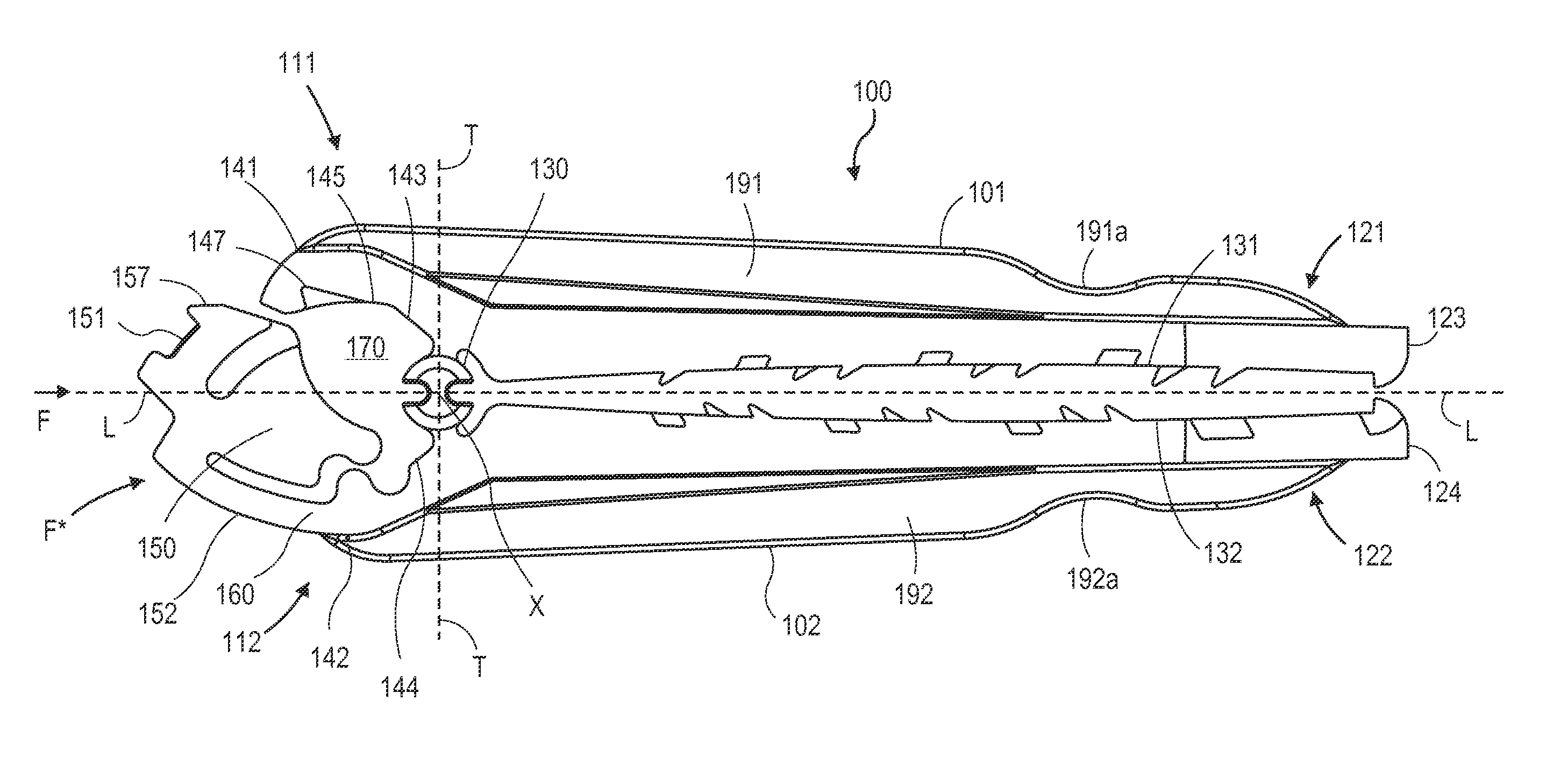
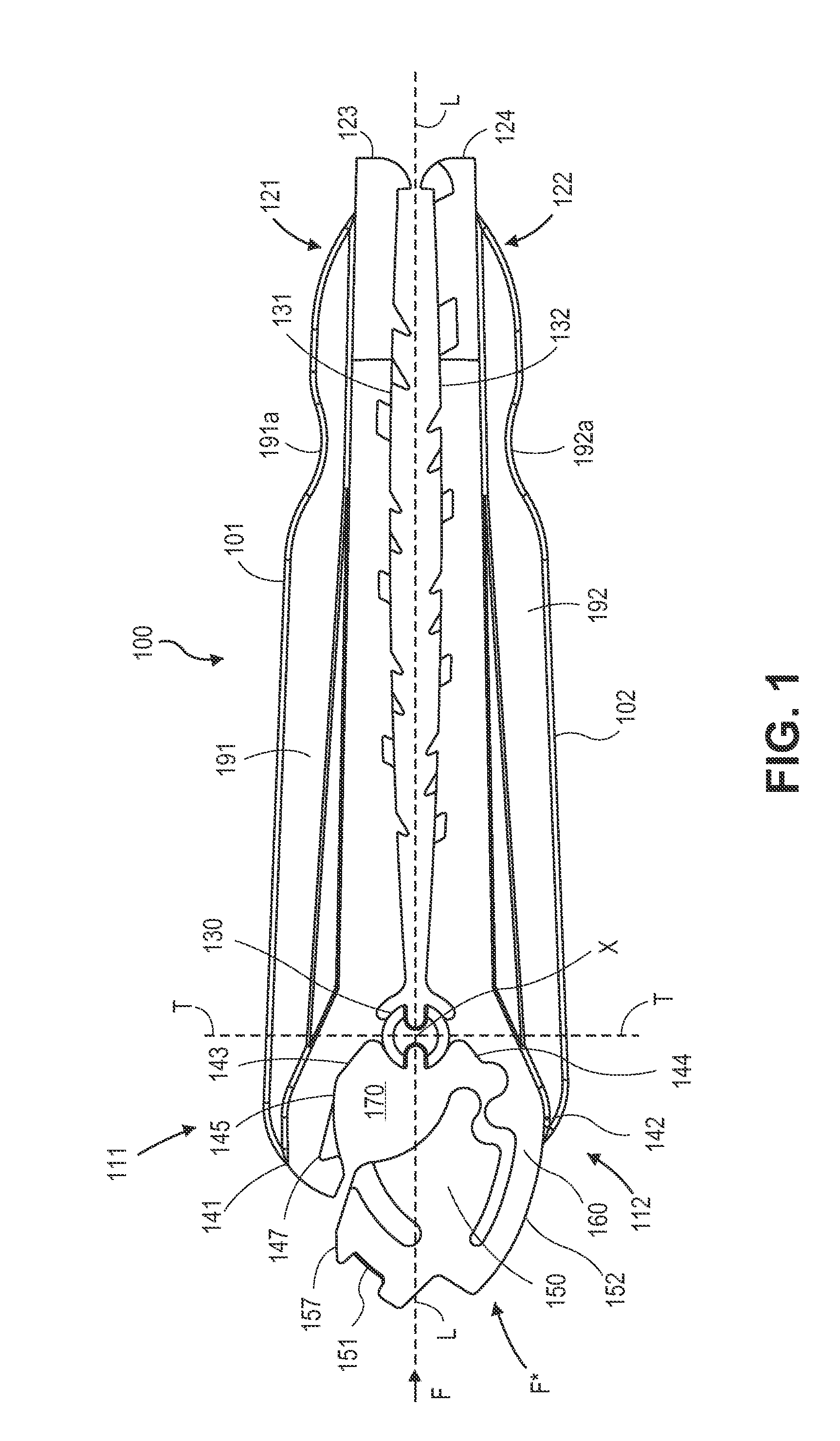
[0048]FIG. 1 shows a view of a first embodiment of a surgical ligation clip 100 of the present invention. The clip 100 defines a longitudinal axis “L” along its longest dimension and includes a first leg 101 and a second leg 102 each extending along the longitudinal axis L and having proximal 111, 112 and distal 121, 122 end portions with respect to said longitudinal axis. As used throughout herein, the term “proximal” shall refer to the portion of the clips referenced herein which is away from the tips of the clip which open, and “distal” shall refer to the portion of the clip at the tips which open, in accordance with the convention that the clip is inserted distal tip first through an instrument towards an anatomical body to be ligated, such that distal generally refers to the direction away from the user or applier of the su...


PUM


Abstract

A narrow profile surgical ligation clip has two legs with clamping surfaces joined by a hinge near the proximal ends, allowing the clip to reversibly open and close. A locking mechanism is proximal to the hinge to bias or lock the clip closed, including first and second jaw structures spaced on opposite sides of a longitudinal axis of the clip thereby defining a locking space therebetween. In one embodiment, a wedge or buttress body moves by application of an external force applied to a proximal end of the clip towards the hinge to move into the locking space such that one or more outer surfaces or projections of portions of the body fit into or abut against complementary surfaces or other parts of the locking mechanism or clip assembly to bias or lock the clip in a closed position and provide additional closing force to the inner clamping surfaces.

Description

CROSS-REFERENCE TO RELATED APPLICATIONS[0001]This application claims priority to U.S. provisional patent application No. 61 / 534,858, filed on Sep. 14, 2011, and is a continuation-in-part and claims priority to U.S. patent application Ser. No. 13 / 042,864, filed Mar. 8, 2011, currently pending, which claims priority to U.S. provisional patent application No. 61 / 312,156, filed on Mar. 9, 2010, the disclosures of all of which are incorporated by reference in their entireties.FIELD OF THE INVENTION[0002]The present invention relates to medical devices and in particular surgical clips for ligation of vessels or tissue.BACKGROUND[0003]Many surgical procedures require vessels or other fluid ducts or tissue conduits and structures to be ligated during the surgical process, such as, for example, veins or arteries in the human body. For example, many surgical procedures require cutting blood vessels, and these blood vessels may require ligation to reduce bleeding. In some instances, a surgeon ...

Claims


Application Information

Patent Timeline
IPC IPC(8): A61B17/122
CPCA61B17/122A61B17/1227A61B17/0643
Inventor SCHMIDT, PHILIPMONAHAN, DANLABARBERA, BRADWHITING, PAULMORRIS, STEVENCASTRO, SALVATORERAMSEY, MICHAELWILLETT, LYNN
Owner TELEFLEX MEDICAL INC
Why Eureka
Try Eureka