Adapter Stabilization Structure for Bucket Lip

a technology of adapter and stabilization structure, which is applied in the direction of soil-shifting machine/dredger, construction, etc., can solve the problems that the meeting of these two design criteria is often less than entirely satisfactory

Inactive Publication Date: 2013-09-26
HENSLEY INDUSTRIES INC
View PDF7 Cites 4 Cited by
  • Summary
  • Abstract
  • Description
  • Claims
  • Application Information

AI Technical Summary

Problems solved by technology

Previous attempts to meet these two design criteria have often proven to be less than entirely satisfactory due to undesirably high expense and / or complexity.

Method used


Image

  • Adapter Stabilization Structure for Bucket Lip
  • Adapter Stabilization Structure for Bucket Lip
  • Adapter Stabilization Structure for Bucket Lip

Examples


Embodiment Construction

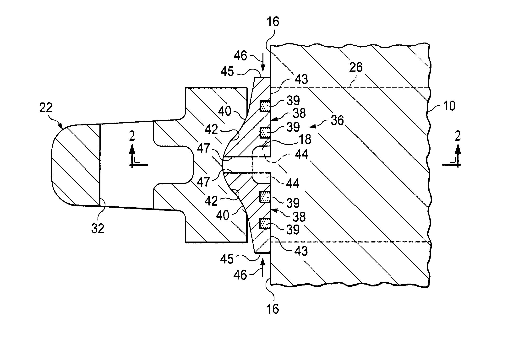
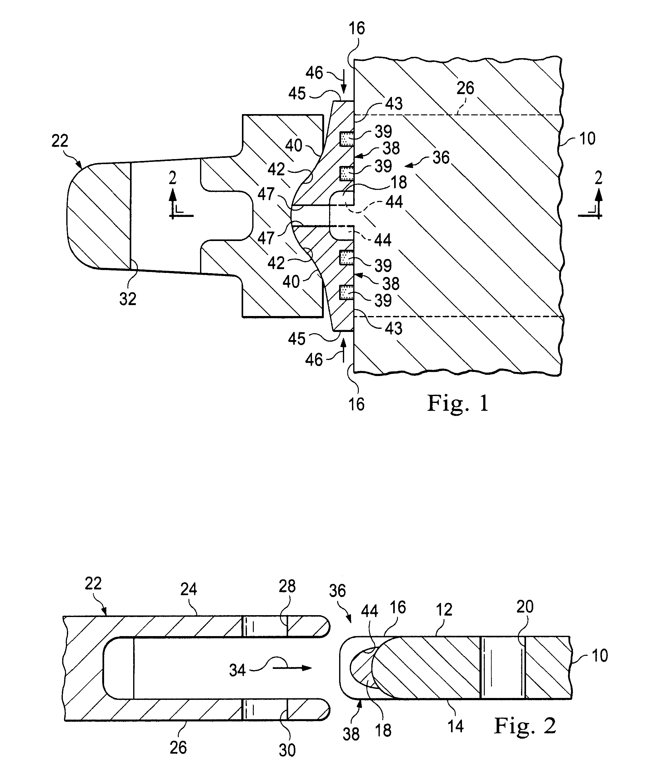
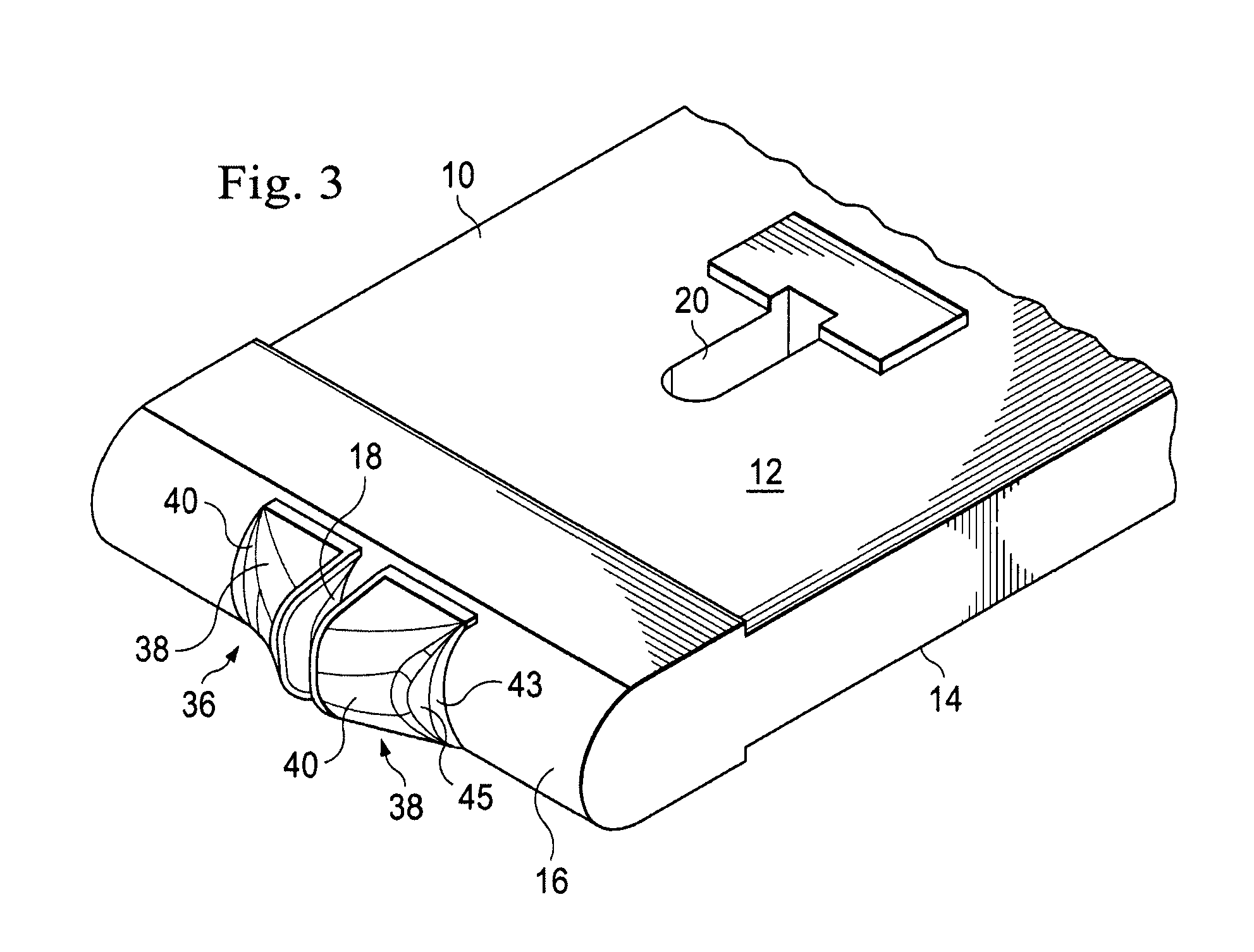
[0008]Turning now to the drawings, a bottom metal excavating bucket lip 10 has top and bottom sides 12 and 14, a front edge 16, and a series of forwardly extending stabilizing projections 18 (only one of which is visible) spaced apart along the length of the front lip edge 16. Spaced rearwardly apart from the front lip edge 16 are a series of connector openings 20 (only one of which is visible) extending downwardly through the lip 10 and aligned with its stabilizing projections 18.

[0009]A wear member, representatively in the form of an adapter 22, is removably securable to the front lip edge 16 to form therewith an earth engaging assembly as shown in FIG. 1. Adapter 22 has a pair of rearwardly projecting vertically spaced apart top and bottom legs 24,26 having aligned connector openings 28,30 (see FIG. 2) vertically extending therethrough. Another connector opening 32 (see FIG. 1) horizontally extends through a front or nose portion of the adapter 22 for use in removably connecting ...


PUM


Abstract

A ground engaging support structure such as an adapter is mounted on the front edge of an excavating bucket lip in a manner inhibiting side-to-side movement of the installed adapter, and shielding the front bucket lip edge from operational wear at the adapter installation location using opposing tapered block members secured to the front lip edge for movement toward a forwardly projecting stabilizing portion of the lip edge. As the adapter is telescoped onto the front lip edge over its stabilizing projection, correspondingly tapered portions of the adapter engage the block members and move them toward one another and toward the stabilizing projection. Rear leg portions of the adapter are then suitably secured to the bucket lip. The repositioned block members interposed between the adapter the front bucket lip edge then inhibit side-to-side shifting of the installed adapter while also shielding the lip edge from operational abrasion wear.

Description

CROSS-REFERENCE TO RELATED APPLICATION[0001]The present application claims the benefit of the filing date of provisional U.S. patent application No. 61 / 613,719 filed Mar. 21, 2012. The entire disclosure of the provisional application is hereby incorporated herein by this reference.BACKGROUND OF THE INVENTION[0002]The present invention relates generally to ground engaging apparatus and, in a representative embodiment thereof, more particularly provides specially designed apparatus for (1) inhibiting undesirable side-to-side movement of a wear member support structure, such as an adapter, relative to a front bucket lip edge on which the adapter is mounted, and (2) shielding the bucket lip edge from operational wear at the wear member mounting location thereon.[0003]In ground engaging arts such as excavation and mining it is common practice to secure a support structure, such as an adapter to which a wear member (such as a replaceable tooth point) may in turn be mounted, to a front edg...

Claims


Application Information

Patent Timeline
Patent Type & Authority Applications(United States)
IPC IPC(8): E02F9/28
CPCE02F9/2825E02F9/2883
Inventor CAMPOMANES, PATRICK
Owner HENSLEY INDUSTRIES INC
Why Eureka
Try Eureka