Expansion valve with variable opening degree

Inactive Publication Date: 2013-09-26
DANFOSS AS
View PDF10 Cites 1 Cited by
  • Summary
  • Abstract
  • Description
  • Claims
  • Application Information

AI Technical Summary

Benefits of technology

The patent aims to provide an expansion valve that allows for adjustable opening without causing significant manufacturing costs. The goal is to create an affordable expansion valve that remains efficient and easy to operate.

Problems solved by technology

However, it is not possible to adjust the supply of refrigerant to the evaporator, e.g. in response to a measured value of the superheat of refrigerant leaving the evaporator, because it is not possible to adjust the opening degree.
However, thermostatic expansion valves are relatively expensive, and they are therefore normally not applied in low cost vapour compression systems.
Furthermore, in the case that a two step compressor is used, a larger opening degree is required at low capacity, and thereby low differential pressure, than at high capacity, and thereby high differential pressure.

Method used


Image

  • Expansion valve with variable opening degree
  • Expansion valve with variable opening degree
  • Expansion valve with variable opening degree

Examples


first embodiment

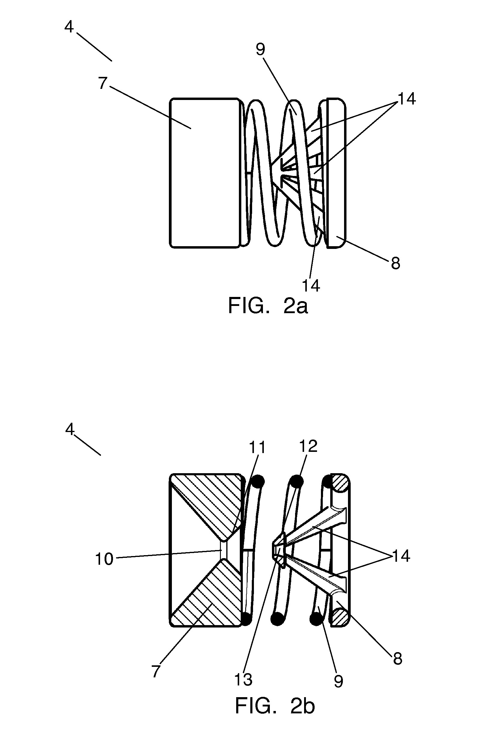
[0046]FIG. 2a is a side view of an expansion valve 4 according to the invention. The expansion valve 4 comprises a first valve member 7 and a second valve member 8. The first valve member 7 and the second valve member 8 are arranged in such a manner that they may perform relative movements. This will be described further below with reference to FIGS. 4 and 5. A compressible spring 9 is arranged between the first valve member 7 and the second valve member 8, thereby biasing the first valve member 7 and the second valve member 8 in a direction away from each other.

[0047]In FIG. 2a the first valve member 7 and the second valve member 8 are arranged in a first relative position, where a distance is defined between the first valve member 7 and the second valve member 8. It is clear from FIG. 2a that it is possible to compress the compressible spring 9 further, thereby moving the first valve member 7 and the second valve member 8 towards each other, against the spring force of the compres...

second embodiment

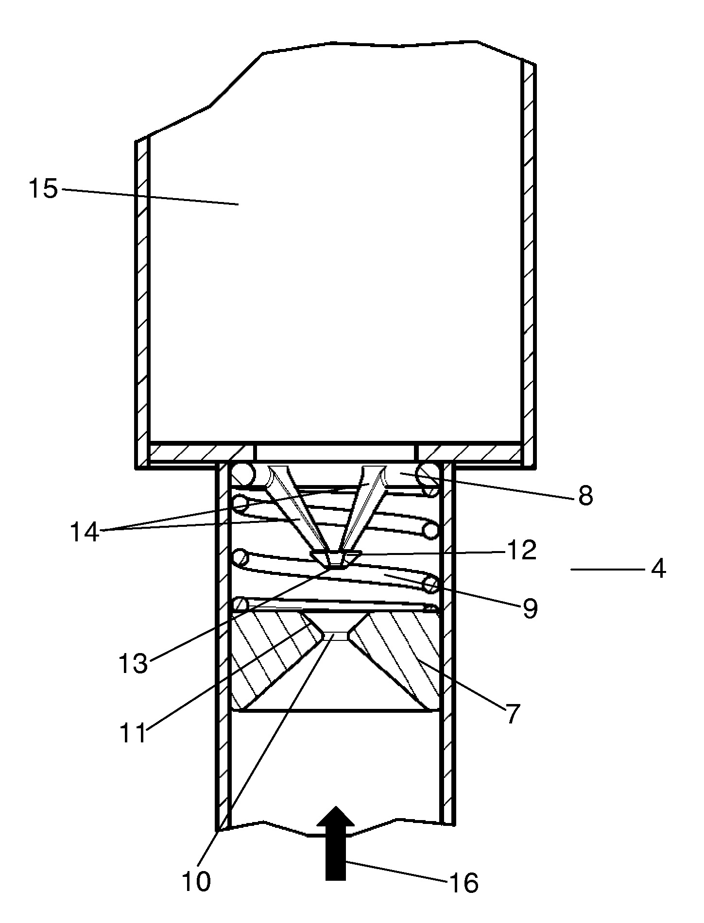
[0058]FIG. 8 is a cross sectional view of an expansion valve 4 according to the invention. The expansion valve 4 is arranged in a refrigerant path 15 of a vapour compression system. The expansion valve 4 comprises a first valve member 7 and a second valve member 8. The second valve member 8 is arranged substantially immovable relatively to the refrigerant path 15, and the first valve member 7 is arranged movably relative to the second valve member 8. A compressible spring 9 is arranged between the first valve member 7 and the second valve member 8, biasing the valve members 7, 8 in a direction away from each other.

[0059]The second valve member 8 is provided with an opening 17 defining a fluid passage through the expansion valve 4. The first valve member 7 comprises a protruding element 18 extending in a direction towards the second valve member 8. The protruding element 18 has a conical shape, i.e. the diameter of the protruding element 18 varies along a longitudinal direction of th...


PUM


Abstract

An expansion valve (4) for a vapour compression system (1), and a vapour compression system comprising such an expansion valve (4) are disclosed. The expansion valve (4) comprises a first valve member (7) and a second valve member (8). The first valve member (7) and the second valve member (8) are arranged movably relative to each other, and the relative position of the first valve member (7) and the second valve member (8) determines an opening degree of the expansion valve (4). The first valve member (7) and / or the second valve member (8) is / are automatically movable in response to changes in a differential pressure across the expansion valve (4), the opening degree of the expansion valve (4) thereby being automatically altered in response to changes in the differential pressure across the expansion valve (4). It is ensured that the opening degree of the expansion valve is automatically adjusted to the actual operating conditions, thereby optimising the efficiency of the vapour compression system. Furthermore, this is obtained in a simple manner, without requiring complicated control of the valve.

Description

CROSS REFERENCE TO RELATED APPLICATIONS[0001]This application is entitled to the benefit of and incorporates by reference essential subject matter disclosed in International Patent Application No. PCT / DK2011 / 000143 filed on Nov. 30, 2011 and Danish Patent Application No. PA 2010 01086 filed Nov. 30, 2010.FIELD OF THE INVENTION[0002]The present invention relates to an expansion valve, in particular an expansion valve for a vapour compression system, such as a refrigeration system, an air condition system or a heat pump. The expansion valve of the invention is capable of defining a variable opening degree. The present invention further relates to a vapour compression system comprising such an expansion valve.BACKGROUND OF THE INVENTION[0003]Vapour compression systems, such as refrigeration systems, air condition systems or heat pumps, normally comprise a compressor, a condenser, an expansion device, e.g. in the form of an expansion valve, and an evaporator arranged along a refrigerant...

Claims


Application Information

Patent Timeline
IPC IPC(8): F25B41/06
CPCF25B41/062F16K17/30F25B1/10Y10T137/7787F25B41/325F25B41/38F25B41/33F16K17/02F16K31/12
Inventor THYBO, CLAUSSUSS, JURGEN
Owner DANFOSS AS
Why Eureka
Try Eureka