Device for implementing FM antenna and a mobile terminal
a mobile terminal and antenna technology, applied in the field of wireless communication, can solve the problems of difficult to achieve good clearance, and difficult to achieve the performance of an earphone antenna, so as to improve the reception avoid the decrease of the performance and improve the reception effect of the fm antenna
- Summary
- Abstract
- Description
- Claims
- Application Information
AI Technical Summary
Benefits of technology
Problems solved by technology
Method used
Image
Examples
first embodiment
The First Embodiment
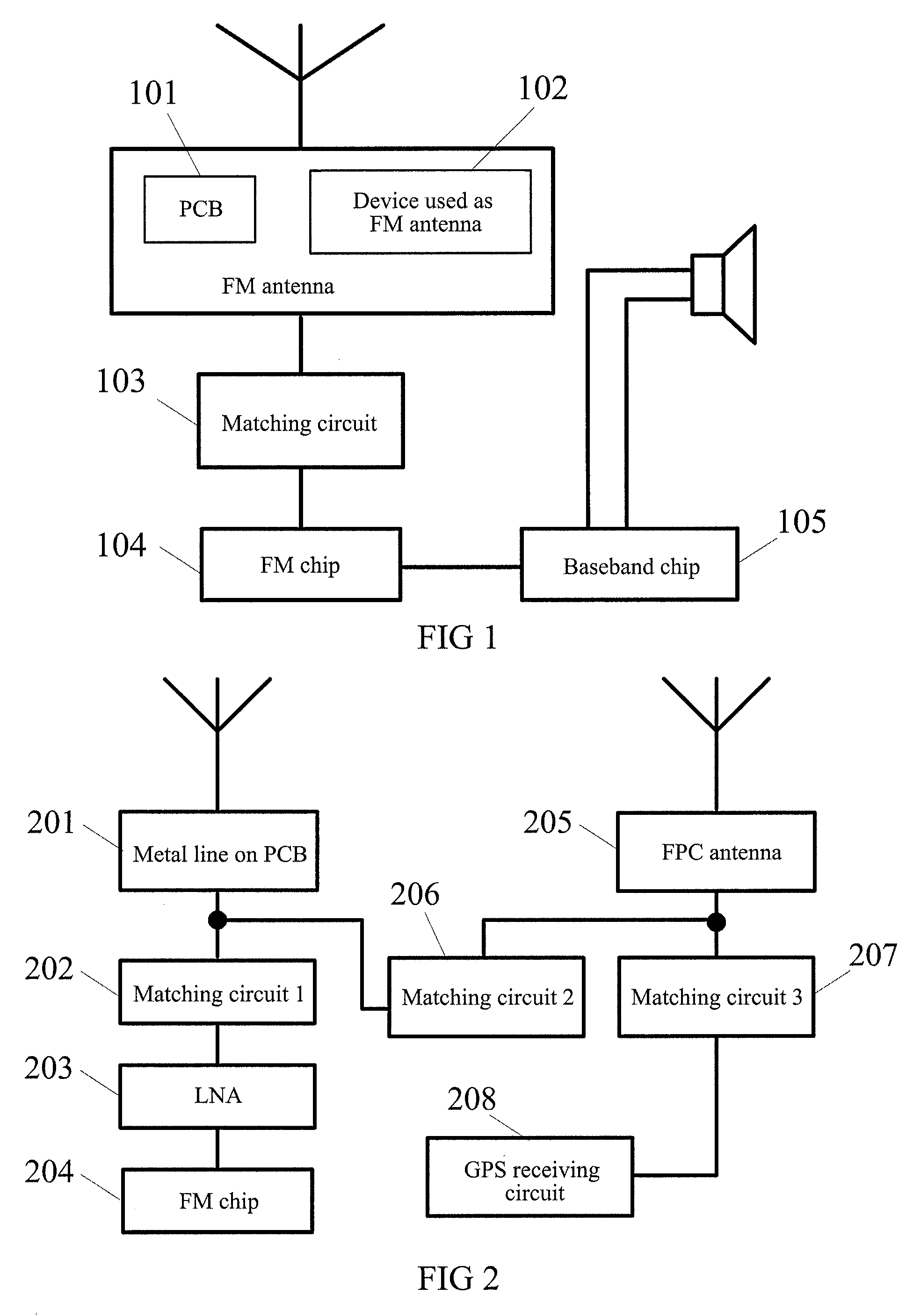
[0034]As shown in FIG. 1, a terminal including a FM antenna device in accordance with this embodiment is provided. The FM antenna device comprises a first Print Circuit Board (PCB) 101 containing a metal line, a device 102 used as FM antenna, a matching circuit 103 connected to the first PCB 101 containing the metal line and the device 102 used as FM antenna respectively.
[0035]The first PCB 101 containing the metal line is used as the first FM antenna and configured to receive FM signals.
[0036]The device 102 that is used as an FM antenna is used as the second FM antenna and configured to receive FM signals.
[0037]The matching circuit 103 is configured to filter the FM signals received by the first FM antenna and the second FM antenna and outputs the filtered FM signals.
[0038]The work process is shown as follows: the FM signals received by the first FM antenna and the second FM antenna are input into the matching circuit; after matched and filtered by the matching ...
second embodiment
The Second Embodiment
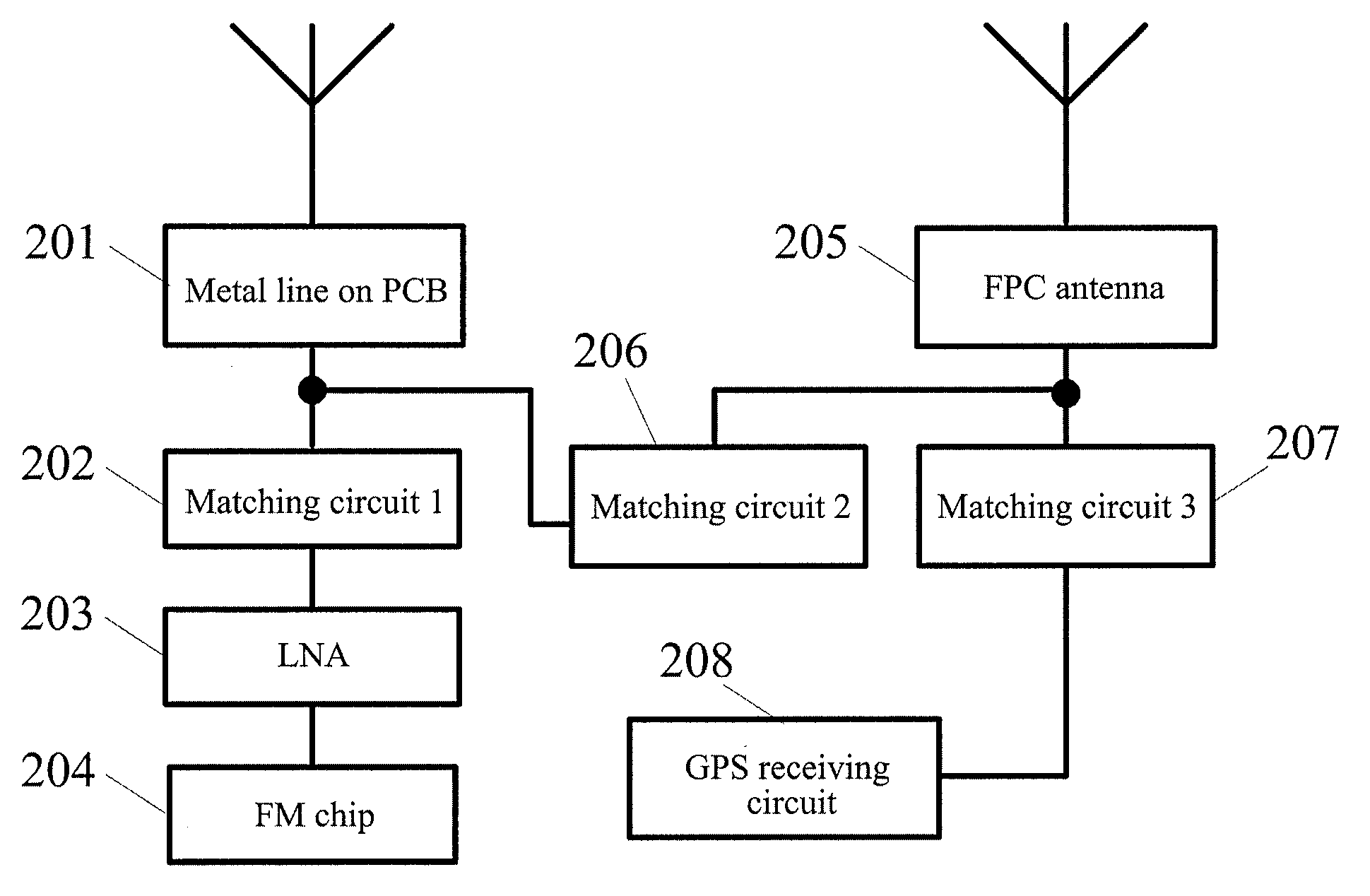
[0042]FIG. 2 shows a realization diagram of an FM antenna in conjunction with the PCB containing the metal line with enhanced FM performance using a section of FPC in a GPS antenna. As shown in FIG. 2, there are three signal paths.
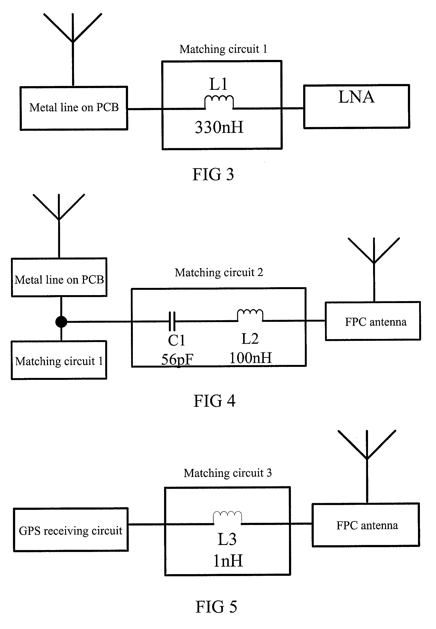
[0043]The first signal path: FM signals received by the PCB containing the metal line 201 are amplified by the low noise amplifier (LNA) 203 through the first matching circuit 202 and input to the FM chip 204. The first signal path is used to receive the FM signals. The first matching circuit 202 is used to isolate GPS signals and match the FM signals.
[0044]The second signal path: FM signals received by the FPC antenna 205 (in this embodiment, a section of FPC in the GPS antenna is used as the FM antenna) are amplified by the LNA 203 through the second matching circuit 206 and input to the FM chip 204.
[0045]The third signal path: GPS antenna is used to receive the GPS signals. The third matching circuit 207 is used to match GPS signals...
third embodiment
The Third Embodiment
[0055]FIG. 6 is one method of layout of a PCB containing a metal line. The metal line (one metal line or one strand of metal lines) may be provided in the following method: more than two vias are provided on the PCB, and the metal line passes through the provided vias successively.
[0056]There are two methods of the layout of the metal line.
[0057]The first method: similar to a zigzag line, up and down directions of the line are alternate (referring to FIG. 6). A fragment of the mental line on the top surface of the PCB is drawn and one via is made, for example, from top to bottom, and a little fragment of the mental line is drawn and a via is made from bottom to top, and a little fragment of the mental line is drawn and then a via is made from top to bottom again. In this method, many vias are on the FM antenna area. The vias are used as parts of the antenna. In this method, it is easy to get the maximum length of the FM antenna on the PCB for the length of the vi...
PUM
 Abstract
Description
Claims
Application Information
 - R&D
- Intellectual Property
- Life Sciences
- Materials
- Tech Scout
- Unparalleled Data Quality
- Higher Quality Content
- 60% Fewer Hallucinations
Browse by: Latest US Patents, China's latest patents, Technical Efficacy Thesaurus, Application Domain, Technology Topic, Popular Technical Reports.
© 2025 PatSnap. All rights reserved.Legal|Privacy policy|Modern Slavery Act Transparency Statement|Sitemap|About US| Contact US: help@patsnap.com


