
Ceiling loudspeaker support system

Active Publication Date: 2013-09-26
RGB SYST INC
View PDF0 Cites 47 Cited by
  • Summary
  • Abstract
  • Description
  • Claims
  • Application Information

AI Technical Summary

Benefits of technology

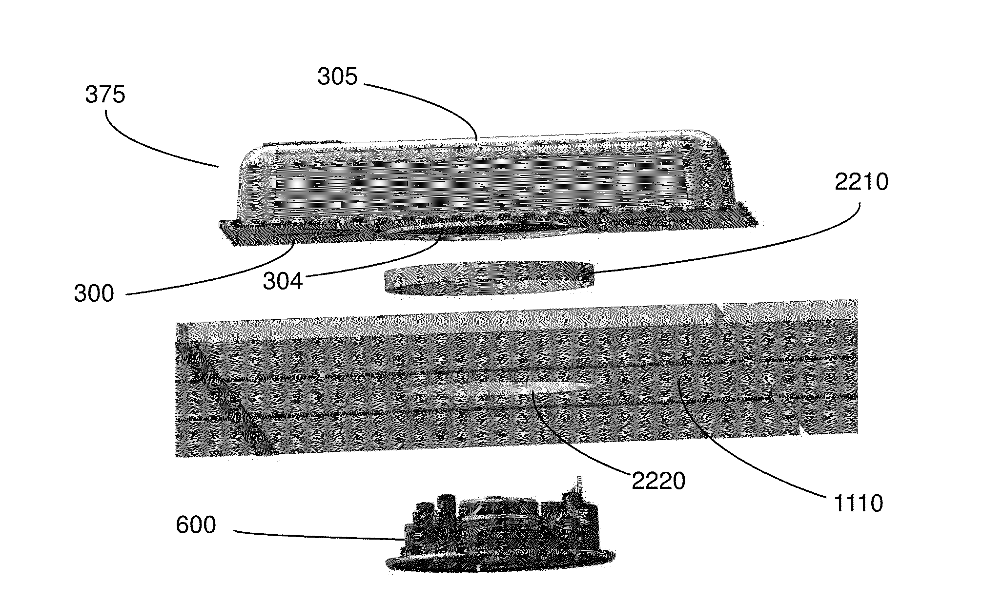
This patent describes a method and apparatus for installing a tile-mounted ceiling speaker system. The apparatus includes a support frame, back box assembly, and a loudspeaker cartridge. The method involves creating a hole in a ceiling tile, placing the support frame and back box assembly on top of the ceiling tile, adding a sealing ring to the hole, connecting wires from an external audio source, connecting wires from the back box, inserting the loudspeaker cartridge into the hole from below, fastening it to the support frame, and adding a grille to it. The invention combines the ease of installation of a lay-in speaker system with the visual appearance of a tile-mounted speaker system. Different loudspeaker cartridges are provided for various configurations. The support frame and back box assembly can accommodate multiple loudspeakers. The invention allows for easy installation and flexibility in configuration options.

Problems solved by technology

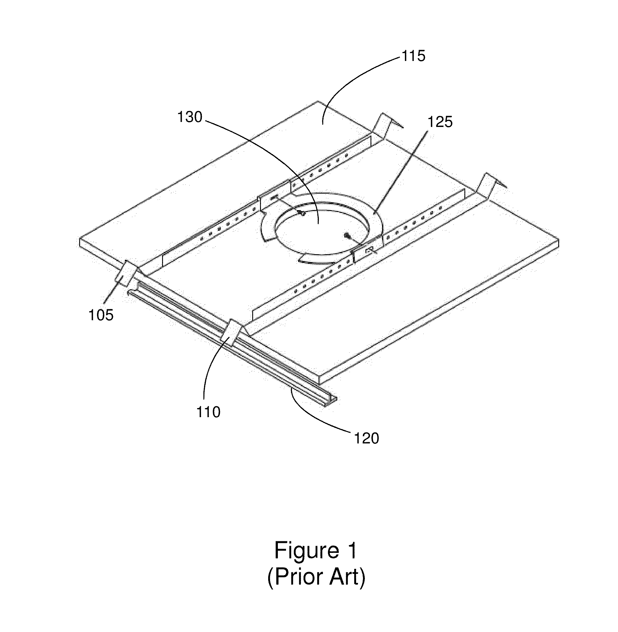
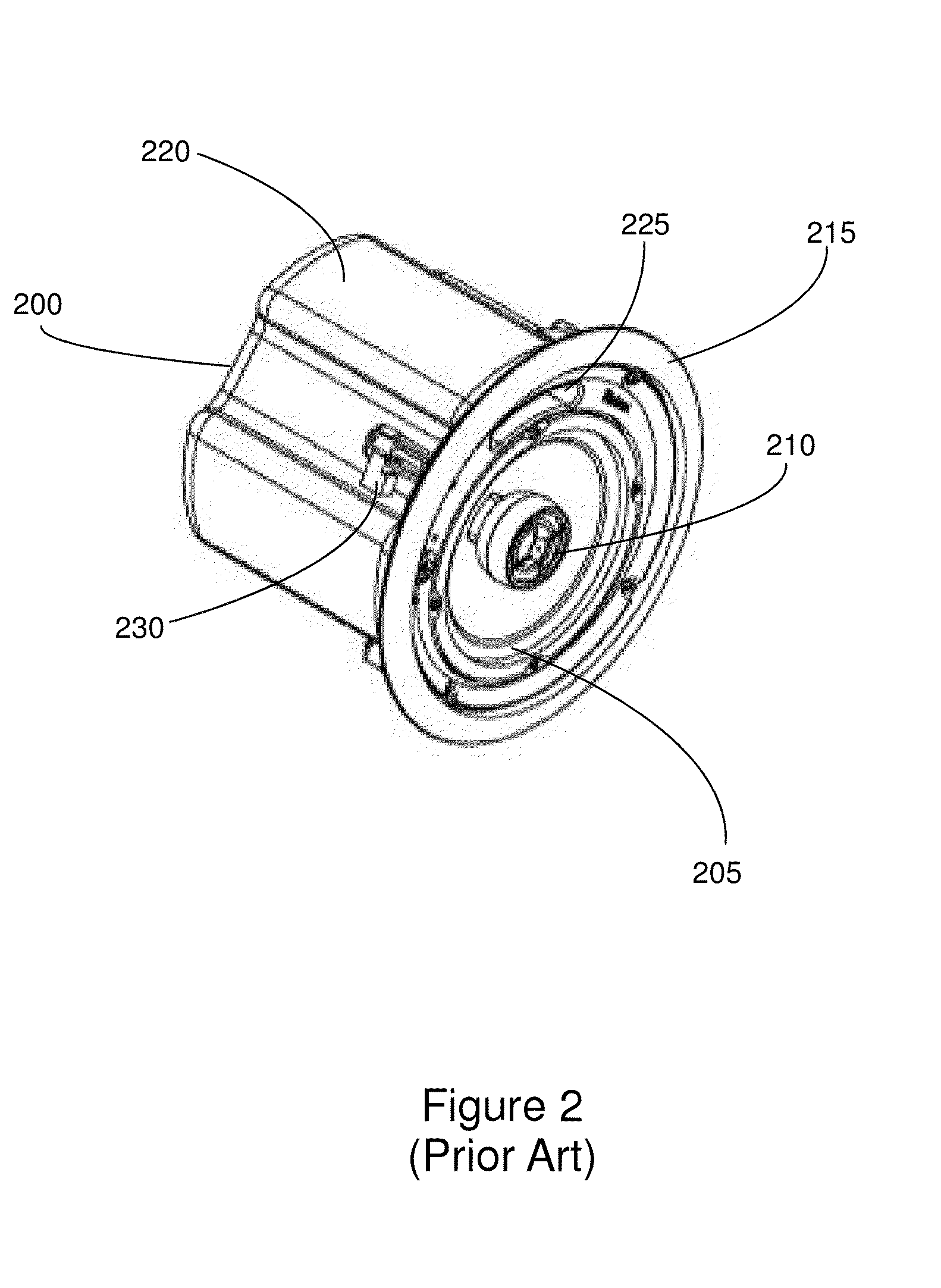
The size of speaker that can be used in this type of loudspeaker system is limited because conventional ceiling tiles have limited structural strength and in some cases are rated by the manufacturers as having no structural strength at all. FIG. 1 shows a modification of this type of ceiling loudspeaker system that adds a support frame that provides additional support for the loudspeaker.

Method used


Image

  • Ceiling loudspeaker support system
  • Ceiling loudspeaker support system
  • Ceiling loudspeaker support system

Examples


Embodiment Construction

[0036]In the following description, numerous specific details are set forth to provide a more thorough description of the present invention. It will be apparent, however, to one skilled in the art, that the present invention may be practiced without these specific details. In other instances, well-known features have not been described in detail so as not to obscure the invention.

[0037]FIG. 3 is an exploded view showing components of a support frame and back box assembly 375 of an embodiment of the present invention. In the embodiment of FIG. 3, components of support frame and back box assembly 375 include a support frame 300, a back box 305, and an outer shield 310.

[0038]In the embodiment of FIG. 3, support frame 300 comprises a metal, plastic, or other material or materials formable into the desired shape and form. In one or more embodiments, support frame 300 is formed as a sheet metal stamping. In the embodiment of FIG. 3, support frame 300 includes a planar portion 301, an open...


PUM


Abstract

The present invention comprises a method and apparatus for installing a tile-mounted ceiling speaker that combines the ease of installation of a lay-in speaker system with the visual appearance of a tile-mounted speaker system. In one or more embodiments, the apparatus of the present invention includes a support frame, back box assembly configured for installation on top of a ceiling tile, a ceiling ring configured to be mounted in an opening in a ceiling tile, and a loudspeaker cartridge configured to be mounted to the support frame through the ceiling tile opening.

Description

CROSS-REFERENCE TO RELATED APPLICATIONS[0001]This patent application is a continuation in part of U.S. patent application Ser. No. 13 / 161,022 filed Jun. 15, 2011, which is a continuation in part of U.S. patent application Ser. No. 13 / 159,801 filed Jun. 14, 2011, issued as U.S. Pat. No. 8,286,749 on Oct. 16, 2012, which is a continuation in part of U.S. patent application Ser. No. 12 / 795,218 filed Jun. 7, 2010, issued as U.S. Pat. No. 8,109,360 on Feb. 7, 2012, which is a continuation in part of U.S. patent application Ser. No. 12 / 355,730 filed Jan. 16, 2009, issued as U.S. Pat. No. 7,866,438 on Jan. 11, 2011, which is a continuation-in-part of U.S. patent application Ser. No. 12 / 163,929 filed Jun. 27, 2008, issued as U.S. Pat. No. 7,861,825 on Jan. 4, 2011, all of which are incorporated by reference in their entirety herein.BACKGROUND OF THE INVENTION[0002](1) Field of the Invention[0003]The present invention relates to a loudspeaker support system for mounting in a suspended ceilin...

Claims


Application Information

Patent Timeline
IPC IPC(8): H04R1/02
CPCH04R2201/021H04R1/02H04R1/2873H04R1/025
Inventor STEWART, JR., WILLIAM C.HUDSON, MICHAELFRERICHS, LARRYSTRONG, CLINTONGAMMON, WELDON
Owner RGB SYST INC
Learn More