Image forming apparatus with conveyance suspension unit

Inactive Publication Date: 2013-09-26
RICOH KK
View PDF2 Cites 5 Cited by
  • Summary
  • Abstract
  • Description
  • Claims
  • Application Information

AI Technical Summary

Benefits of technology

This patent is about an image forming apparatus that can create high-quality images by keeping the speed at which the print medium travels equal to the speed at which the toner image is transferred onto the print medium. This allows for smoother and more complete transfer of the toner image, resulting in better quality images.

Problems solved by technology

This may result in the misalignment of the image and uneven image density, which degrade image quality.
In this case, therefore, the surface speed of the intermediate transfer belt differs from the travel speed of the sheet, resulting in a positional displacement of an image or the like.
Image quality may thus be degraded.
Even with the configuration that causes the transfer roller to follow the movement of the intermediate transfer belt, the existence of a difference in conveyance speed caused by the upstream conveyance unit may degrade image quality.

Method used


Image

  • Image forming apparatus with conveyance suspension unit
  • Image forming apparatus with conveyance suspension unit
  • Image forming apparatus with conveyance suspension unit

Examples


first embodiment

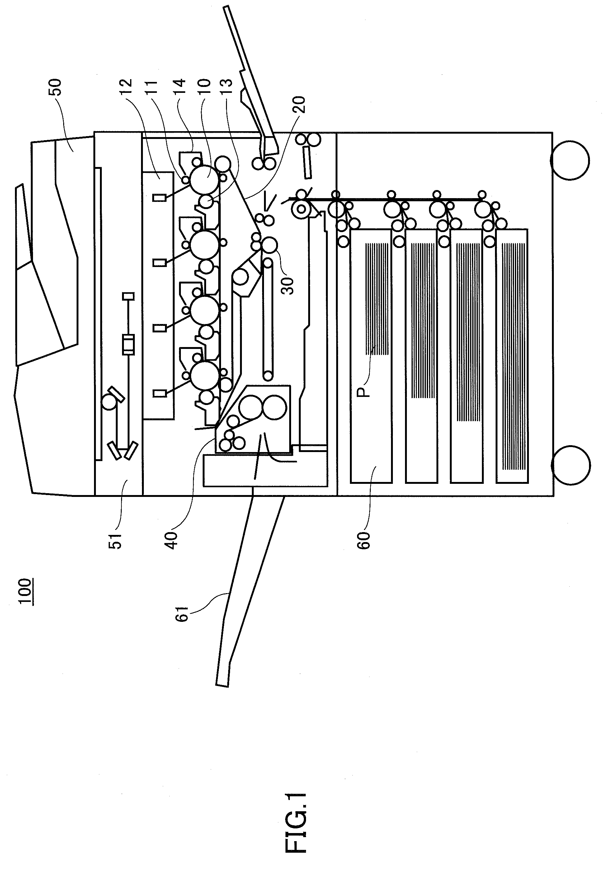
[0023]FIG. 1 is a drawing illustrating an example of the schematic configuration of an image forming apparatus 100 according to a first embodiment.

[0024]The image forming apparatus 100 includes a photo conductor 10, a charging unit 11, an exposure unit 12, a developing unit 13, an intermediate transfer belt 20, a transfer roller 30, a fuser unit 40, an automatic document feeder 50, and a scanner unit 51. The image forming apparatus 100 is a multifunction device that prints an image on a sheet P serving as a print medium stored in a sheet tray 60.

[0025]When the image forming apparatus 100 is to print an image on a sheet P, the charging unit 11 uniformly charges the surface of the photo conductor 10 that is rotating. A document placed in the automatic document feeder 50 is scanned by the scanner unit 51 to produce image data, based on which the exposure unit 12 exposes the surface of the photo conductor 10 to light to create a latent image. The developing unit 13 that has a developing...

second embodiment

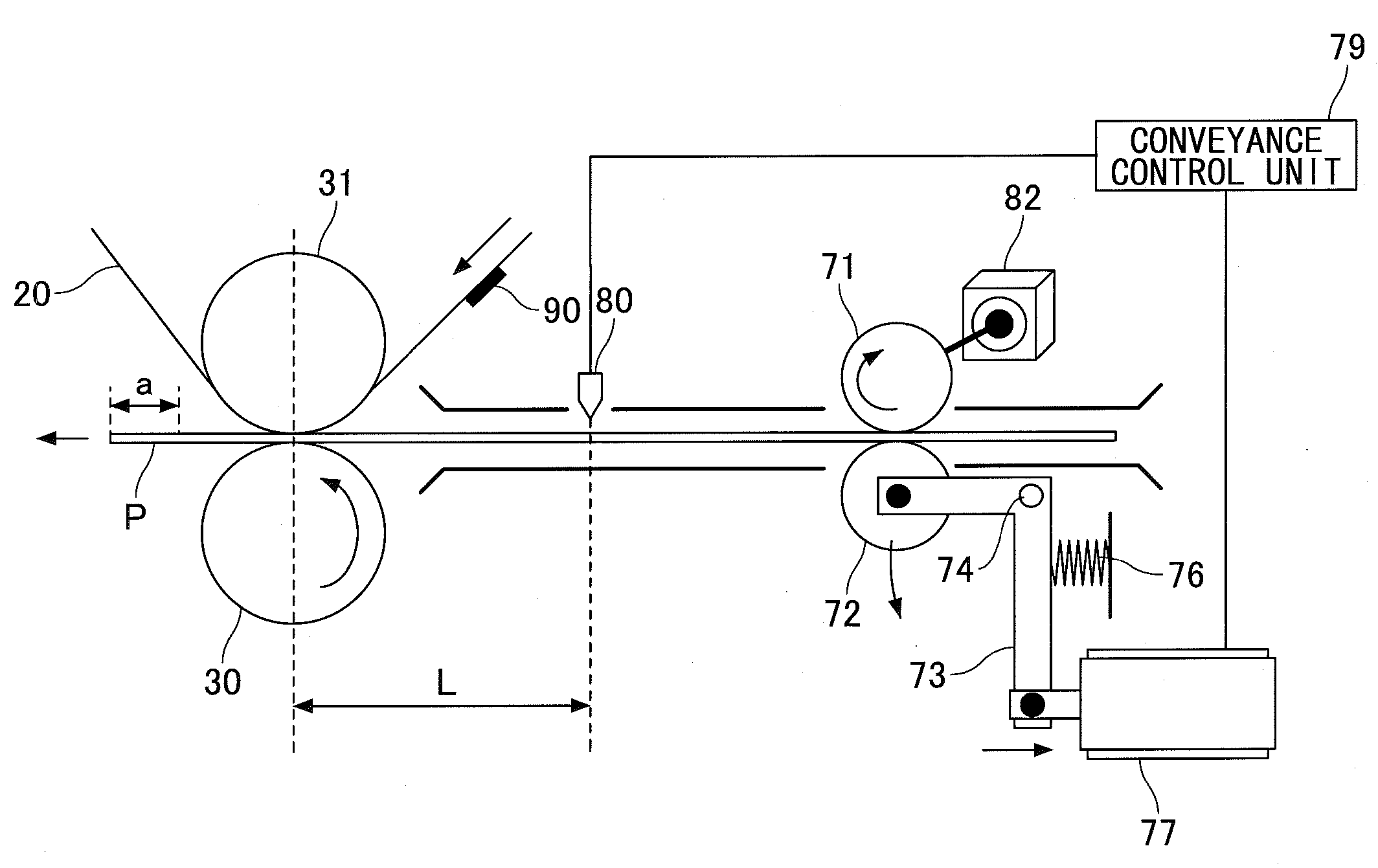
[0053]In the following, a second embodiment will be described with reference to the accompanying drawings. A description will be omitted of the same elements as those of the embodiments already described. The second embodiment differs from the first embodiment in that no electromagnetic clutch is provided between the drive roller 71 and the motor 82, and a separation mechanism is provided that causes the driven roller 72 to move away from the drive roller 71.

[0054]FIG. 4 is a drawing illustrating an example of the schematic configuration of the second transfer unit and an upstream conveyance unit according to the second embodiment.

[0055]As illustrated in FIG. 4, the separation mechanism of the driven roller 72 includes a support member 73, a spring 76, and an eccentric cam 75.

[0056]The support member 73 supports the rotational shaft of the driven roller 72, and is rotatable about a pivot point 74.

[0057]The spring 76 is in contact with the support member 73 on the side of the pivot p...

third embodiment

[0064]In the following, a third embodiment will be described with reference to the accompanying drawings. A description will be omitted of the same elements as those of the embodiments already described. In the third embodiment, the separation mechanism for causing the driven roller 72 to move away from the drive roller 71 has a different configuration than the configuration used in the second embodiment.

[0065]FIG. 6 is a drawing illustrating an example of the schematic configuration of the second transfer unit and an upstream conveyance unit according to the third embodiment.

[0066]As illustrated in FIG. 6, the separation mechanism of the driven roller 72 includes the support member 73, the spring 76, and a solenoid 77.

[0067]The support member 73 supports the rotational shaft of the driven roller 72, and is rotatable about a pivot point 74.

[0068]The spring 76 is in contact with the support member 73 on the side of the pivot point 74 opposite the driven roller 72. The spring 76 serve...


PUM


Abstract

An image forming apparatus includes a drive roller configured to rotate, a driven roller configured to hold and convey a print medium at a gap between the drive and driven rollers, an image carrier configured to have a toner image formed on a surface thereof and to rotate, the image carrier being situated downstream relative to the drive roller and the driven roller in a travel direction of the print medium, a transfer roller configured to hold and convey, at another gap between the image carrier and the transfer roller, the print medium passed from the drive roller and the driven roller to transfer the toner image onto a surface of the print medium, and a conveyance suspension unit to stop the drive roller and the driven roller from applying a drive force to the print medium at a time at which the print medium reaches such another gap.

Description

BACKGROUND OF THE INVENTION[0001]1. Field of the Invention[0002]The disclosures herein relate to an image forming apparatus.[0003]2. Description of the Related Art[0004]An image forming apparatus may use a configuration that transfers a toner image formed on a photo conductor to an intermediate transfer belt. The toner image is then transferred onto a sheet that is placed between the intermediate transfer belt and a transfer roller situated in contact with the intermediate transfer belt. In this manner, a printout is obtained on which the image is printed.[0005]At the time of transferring a toner image onto a sheet, the surface speed of the rotating intermediate transfer belt may differ from the speed of the sheet being conveyed. In such a case, the position of the toner image transferred from the intermediate transfer belt onto the sheet may be displaced. This may result in the misalignment of the image and uneven image density, which degrade image quality. Further, accuracy of ali...

Claims


Application Information

Patent Timeline
IPC IPC(8): G03G15/00
CPCG03G15/0189G03G15/6558G03G15/6561
Inventor UEDA, NAOTONAKURA, MAKOTOTAKAI, SHINGOUEDA, SATOSHIKUDO, KOICHI
Owner RICOH KK
Why Eureka
Try Eureka