Power unit of shaft drive type vehicle

a technology of power unit and shaft drive, which is applied in mechanical equipment, transportation and packaging, and gearing, etc., can solve the problems of difficulty in confirming the preload of damper springs, and achieve the effect of uniform preloading of damper springs, convenient adjustment of the mesh amount of bevel gears, and convenient assembly setting

Active Publication Date: 2013-10-03
HONDA MOTOR CO LTD
View PDF6 Cites 5 Cited by
  • Summary
  • Abstract
  • Description
  • Claims
  • Application Information

AI Technical Summary

Benefits of technology

[0020]According to the power unit of the shaft drive type vehicle of the first aspect of the present invention, the first flange portion is provided on the output shaft side portion of the extended shaft, and the cam damper mechanism is provided in a completed form on the extended shaft by fastening the first bearing to an other end portion of the extended shaft, which thereby can fix the compression amount of the damper spring only with the assembly on the extended shaft side.
[0021]By fixing the extended shaft, which is assembled in such manner, to the bevel gear holder together with the first bearing, when attaching the bevel gear holder to the bevel gear case, the adjustment of the mesh amount of a pair of bevel gears do not have an effect on the compression amount of the damper spring even when adjusting the shim at a joint face between the bevel gear holder and the bevel gear case.
[0022]Therefore, it is possible both to keep the uniform preloading of the damper spring and to facilitate the adjustment of the mesh amount of the bevel gears.
[0023]According to the second aspect of the present invention, in addition to the effect of the first aspect, it is possible to easily set the assembly of the second flange portion by separating the collar member, and to close the load for fastening the first bearing with the fastening member, the extended shaft, the stepped portion of the extended shaft, the first cylindrical portion of the collar member, the second flange portion of the collar member, the inner race of the first bearing and the retainer plate member in order, and to securely fasten the first bearing.
[0024]In addition, the cam member of the cam damper mechanism has the axial force, which is applied on the damper spring, is supported on the extended shaft via at least one of the bevel gears, the second flange portion of the collar member, the inner race of the first bearing, the retainer plate member and the fastening member, which thereby can fix the position in the axial direction of the cam member.
[0025]According to the third aspect of the present invention, in addition to the effect of the second aspect, by setting a part on the side, which confronts the second flange portion of the collar member, as the contact surfaces, the area of the contact surfaces is reduced and the lubricating oil is held in the gaps of the other part thereof, which thereby reduces the frictional resistance during a phase shifting rotation against the extended shaft of the cam member as a result of the operation of the cam damper mechanism.

Problems solved by technology

As a result, since both the shim and the damper spring are fastened and compressed together, there is a difficulty in confirming the preload of the damper spring and is a problem of the change in preload according to the thickness of shim.

Method used


Image

  • Power unit of shaft drive type vehicle
  • Power unit of shaft drive type vehicle
  • Power unit of shaft drive type vehicle

Examples


Embodiment Construction

[0038]An embodiment of the present invention will now be described, with reference to the drawings. Throughout this description, relative terms like “upper”, “lower”, “above”, “below”, “front”, “back”, and the like are used in reference to a vantage point of an operator of the vehicle, seated on the driver's seat and facing forward. It should be understood that these terms are used for purposes of illustration, and are not intended to limit the invention.

[0039]In other words, in the description and scope of claims of the specification, directions such as front and rear, left and right, and upper and lower are formed with reference to the direction the vehicle body with the power unit of the shaft drive type vehicle installed in the shaft drive type vehicle according to an illustrative embodiment of the present invention.

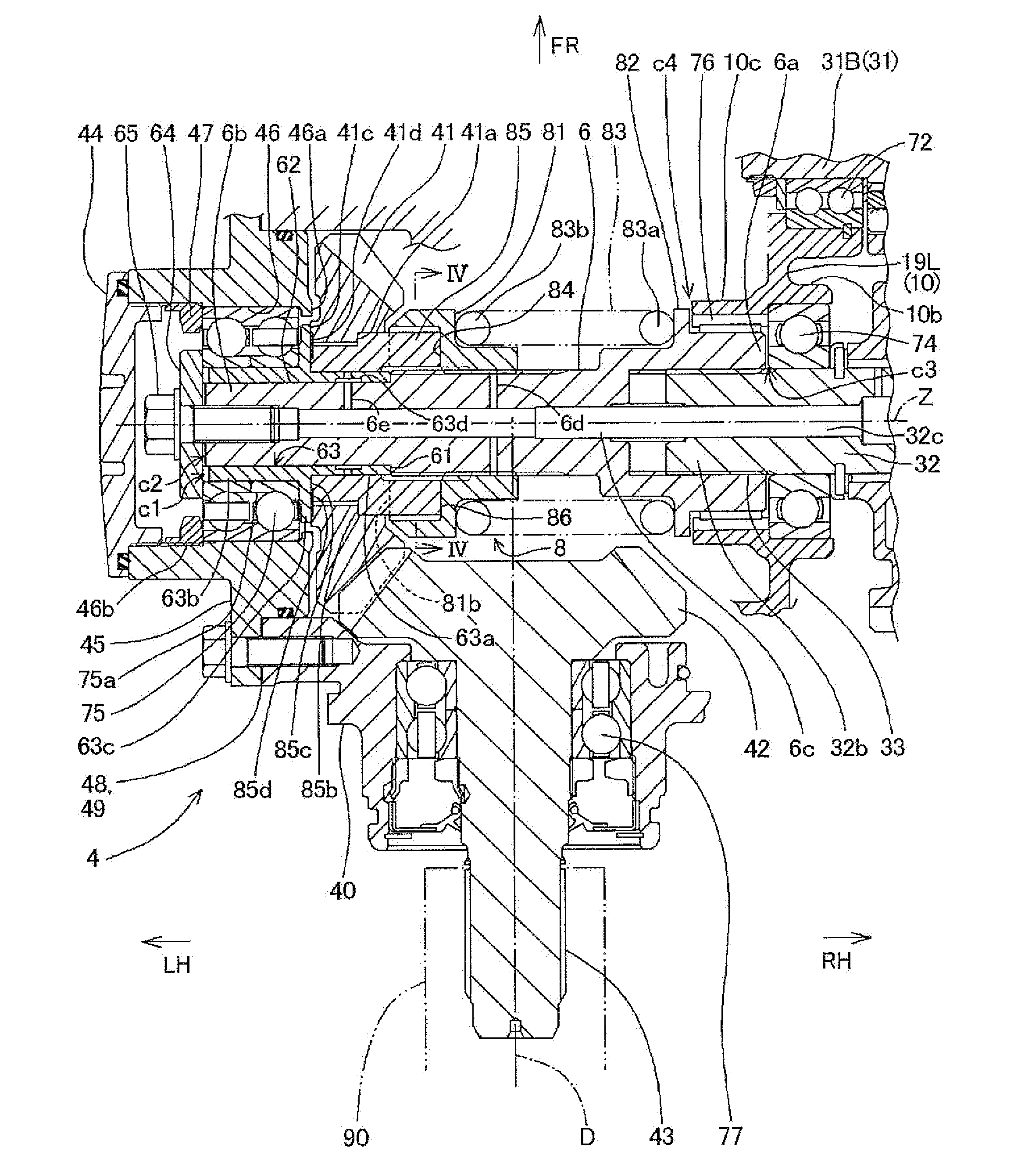
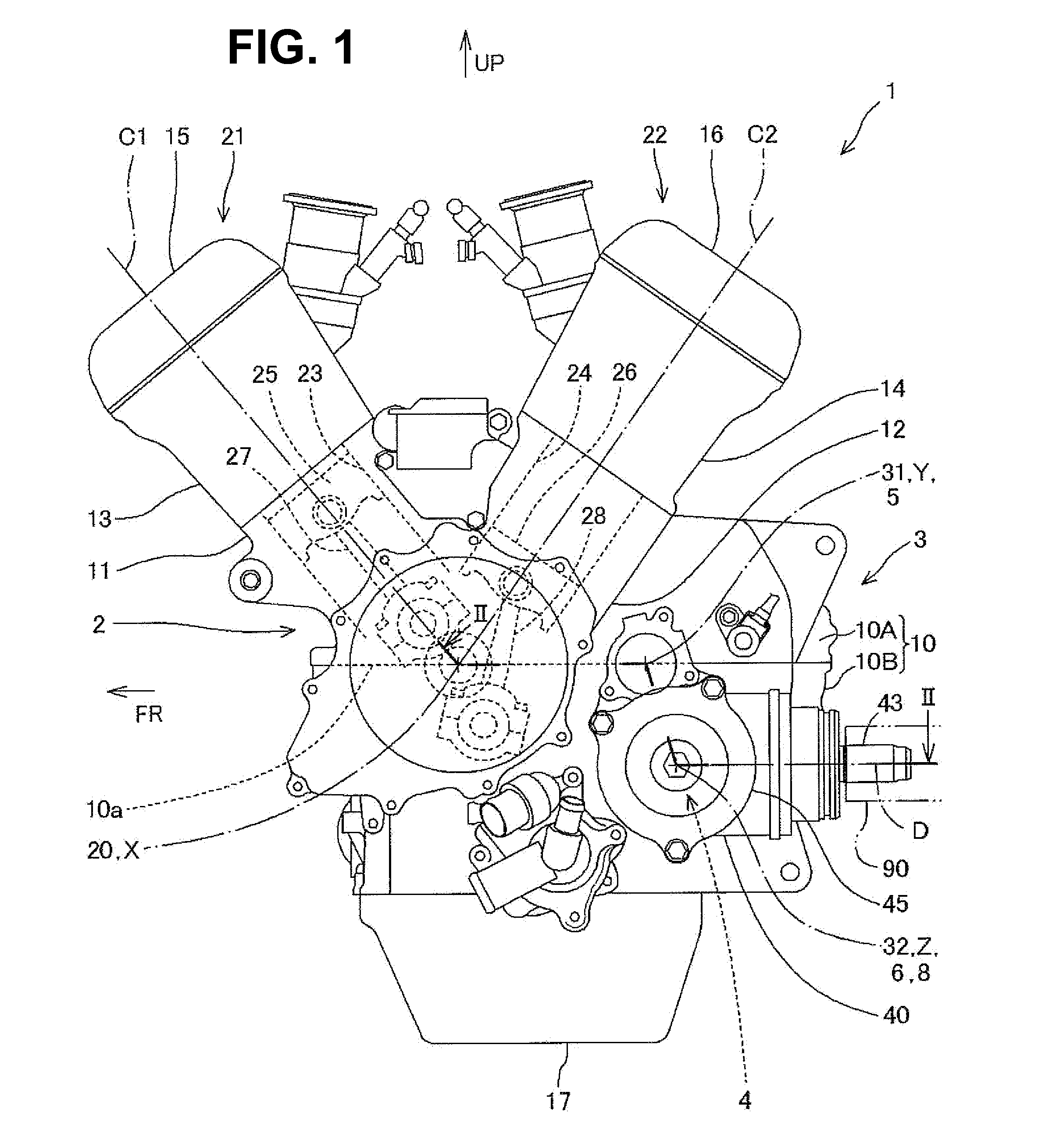
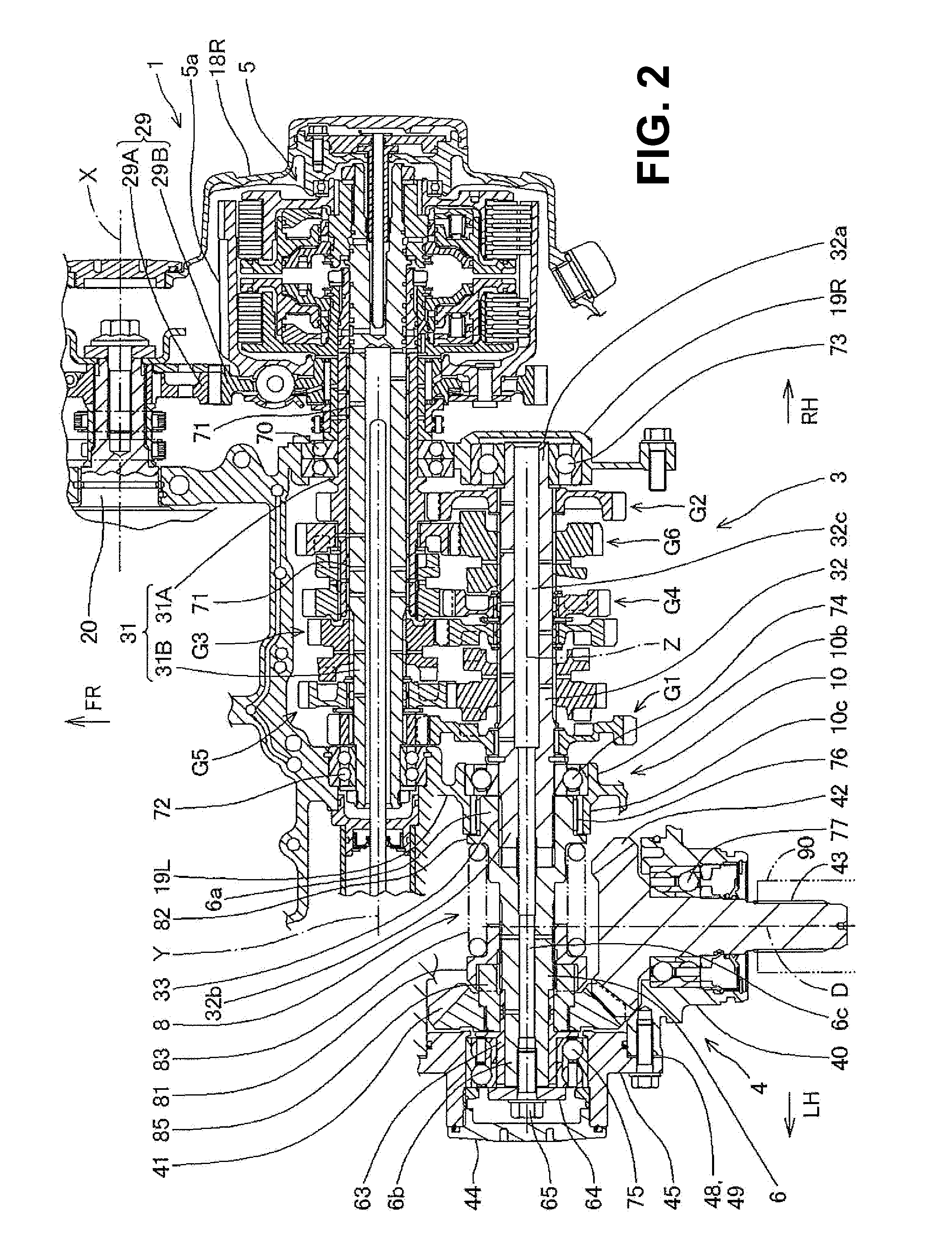
[0040]With reference to FIGS. 1 to 5, a power unit of a shaft drive type vehicle according to the illustrative embodiment of the present invention will now be descri...


PUM


Abstract

A power unit includes a cam damper mechanism having a cam member reciprocally and unrotatably provided on one of a pair of bevel gears, and rotatably provided on an extended shaft; a lifter member slidably and unrotatably provided on the extended shaft in an axial direction; a damper spring configured such that one end portion thereof is supported on a first flange portion of the extended shaft, and the other end portion thereof biases the lifter member toward the cam member in an axial direction by abutting on the lifter member, and the biasing force is supported by the one bevel gear. The extended shaft has the one of the bevel gears and the cam damper mechanism between the first flange portion and a first bearing, and is accommodated in the bevel gear case so as to be fixed to a bevel gear holder along with the first bearing.

Description

CROSS-REFERENCE TO RELATED APPLICATIONS[0001]The present invention claims priority under 35 USC 119 based on Japanese patent application No. 2012-073963, filed on Mar. 28, 2012. The entire subject matter of this priority document, including specification claims and drawings thereof, is incorporated by reference herein.BACKGROUND OF THE INVENTION[0002]1. Field of the Invention[0003]The present invention relates to a power unit of a shaft drive type vehicle. More particularly, the present invention relates to a power unit for shaft drive type vehicle in which an extended shaft, which is provided on a shaft end portion of an output shaft of the power unit, has a cam damper mechanism and a pair of bevel gears connecting a drive shaft system.[0004]2. Description of the Background Art[0005]There is a known power unit of a shaft drive type motorcycle, in which a countershaft of a transmission constitutes an output shaft, an extended shaft is coaxially provided on a shaft end portion of the...

Claims


Application Information

Patent Timeline
Patent Type & Authority Applications(United States)
IPC IPC(8): F16H1/12F16F7/06
CPCF16H1/12Y10T74/19693B62M17/00F16F7/06
Inventor MURAO, MASAYATERADA, KOJIWATANABE, JUNYA
Owner HONDA MOTOR CO LTD
Why Eureka
Try Eureka