Lip sealing device for piston flushing valve

A technology of lip seals and flushing valves, which is applied to the sealing of engines, flushing equipment with water tanks, valve operation/release devices, etc., and can solve problems such as changes in friction and uneven flushing volume

Inactive Publication Date: 2006-11-22
SLOAN VALVE COMPANY
View PDF0 Cites 0 Cited by
  • Summary
  • Abstract
  • Description
  • Claims
  • Application Information

AI Technical Summary

Problems solved by technology

Another consequence is that the seal itself will wear over time, causing a change in the friction bet

Method used


Image

  • Lip sealing device for piston flushing valve
  • Lip sealing device for piston flushing valve
  • Lip sealing device for piston flushing valve

Examples


Embodiment Construction

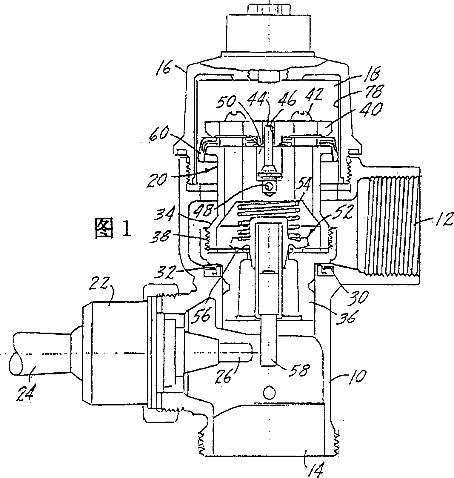
[0037] [37] The present invention relates to an improved seal for a piston flush valve. In existing devices of this type, which are basically made by molding an elastomer over a brass insert, the torque applied by the screw connecting the seal into the piston part can cause the upper edge of the seal to The lower lip expands, reducing the gap between the lip seal and the bore of the flushometer body. This in turn increases the friction between the seal and the bore. Due to the increased friction, the duration of the flush cycle also increases, increasing the amount of water delivered during the operating cycle. Friction is not a problem for the upstroke of the piston because there is a sufficient pressure differential to push the piston upward and the geometry of the seal allows it to move freely in that direction. Friction becomes problematic for the downstroke of the piston, because pressure slowly builds up in the cavity above the piston component, and the geometry of the...


PUM


Abstract

The present invention relates to a piston member for a flush valve for lavatories and urinals, the flush valve having a valve body with an inlet and an outlet, and a valve seat at the outlet. The piston member is movable within the valve body towards and away from the valve seat to control flow from the inlet to the outlet. In the piston part there is a safety valve for communicating the pressure chamber of the flushing valve with the outlet of the flushing valve. The piston member has an outwardly directed lip seal which bears against the inner wall of the valve body and the lip seal is retained between facing elements of the piston member. The lip seal includes an insert, and an elastomer covering and substantially enveloping the insert. Both the elastomer and the insert have a portion extending towards the flush valve body, and the insert has a support element which contacts a facing element of the piston member, transferring load from such element from the lip Remove from the elastomeric body of the shaped seal.

Description

technical field [0001] [01] This invention relates to piston flushometers or flushometers, and more particularly, to improved seals for piston components. During operation of the flush valve, the piston member reciprocates and the lip seal creates a dynamic barrier between the pressure chamber above the piston member and the discharge port below the piston member. An advantage of the piston seal of the present invention is that it requires only less stringent assembly criteria and provides a seal with greatly extended service life and improved flush volume consistency. [0002] [02] The lip seal of the present invention acts as a support to keep the piston member sliding along its axis into the bore of the flush valve. The specific seal design reduces the effect of retaining helical torque on the lip geometry. The lip seal includes an insert and an elastomer molded onto the insert. The function of this insert is to reinforce the seal itself. The injection molded parts of t...

Claims


Application Information

Patent Timeline
IPC IPC(8): E03D1/34F16J15/10F16K31/383
CPCF16J15/104F16K31/3835
Inventor 理查德·A·诺尔捷
Owner SLOAN VALVE COMPANY
Why Eureka
Try Eureka