Apparatus and method for controlling exhaust gas recirculation

a technology of exhaust gas recirculation and control apparatus, which is applied in mechanical apparatus, electrical control, machines/engines, etc., can solve the problems of increasing product cost and complex engine configuration, and achieve the effect of minimizing the number of mounted sensors

Active Publication Date: 2013-10-03
HYUNDAI MOTOR CO LTD +1
View PDF4 Cites 4 Cited by
  • Summary
  • Abstract
  • Description
  • Claims
  • Application Information

AI Technical Summary

Benefits of technology

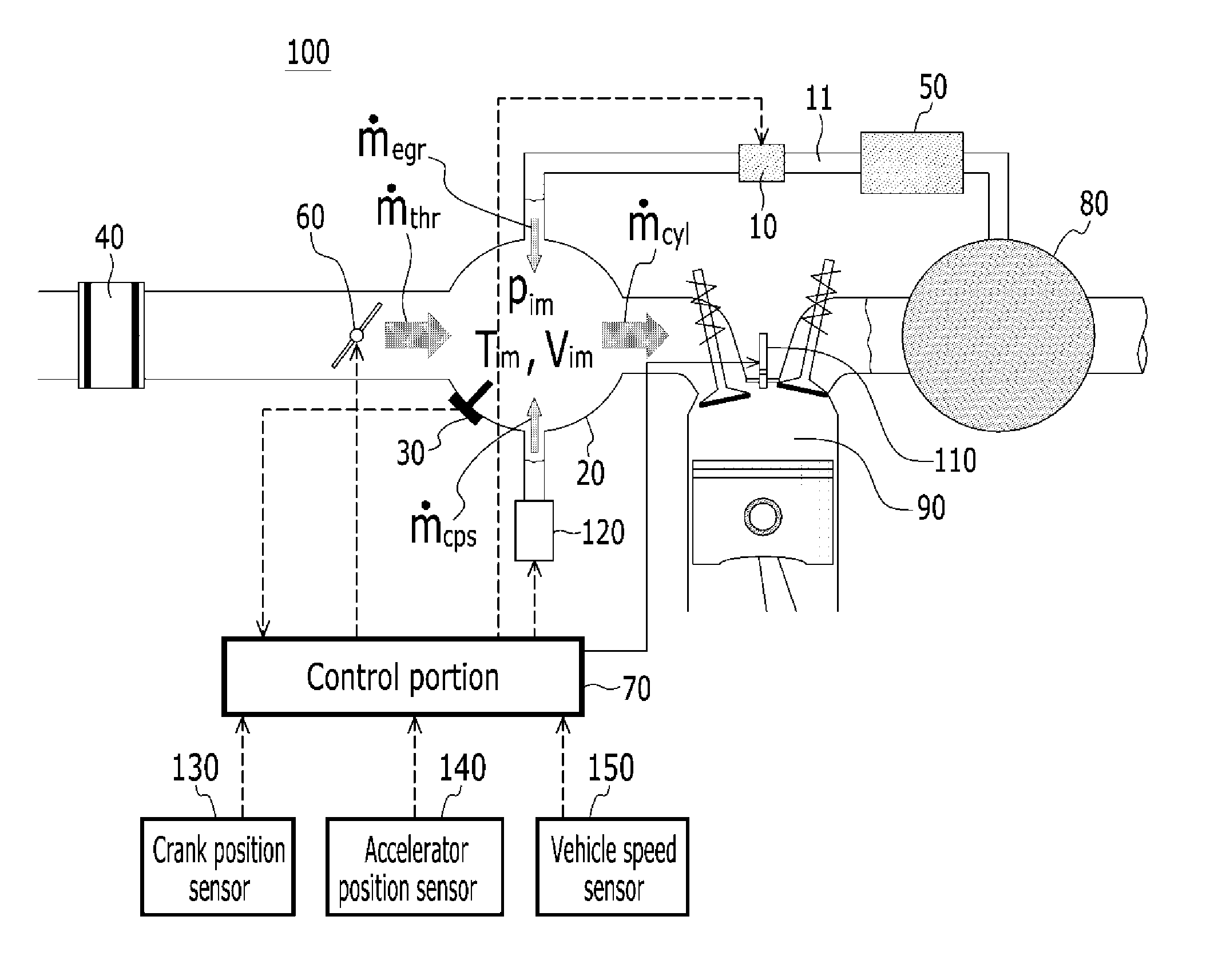
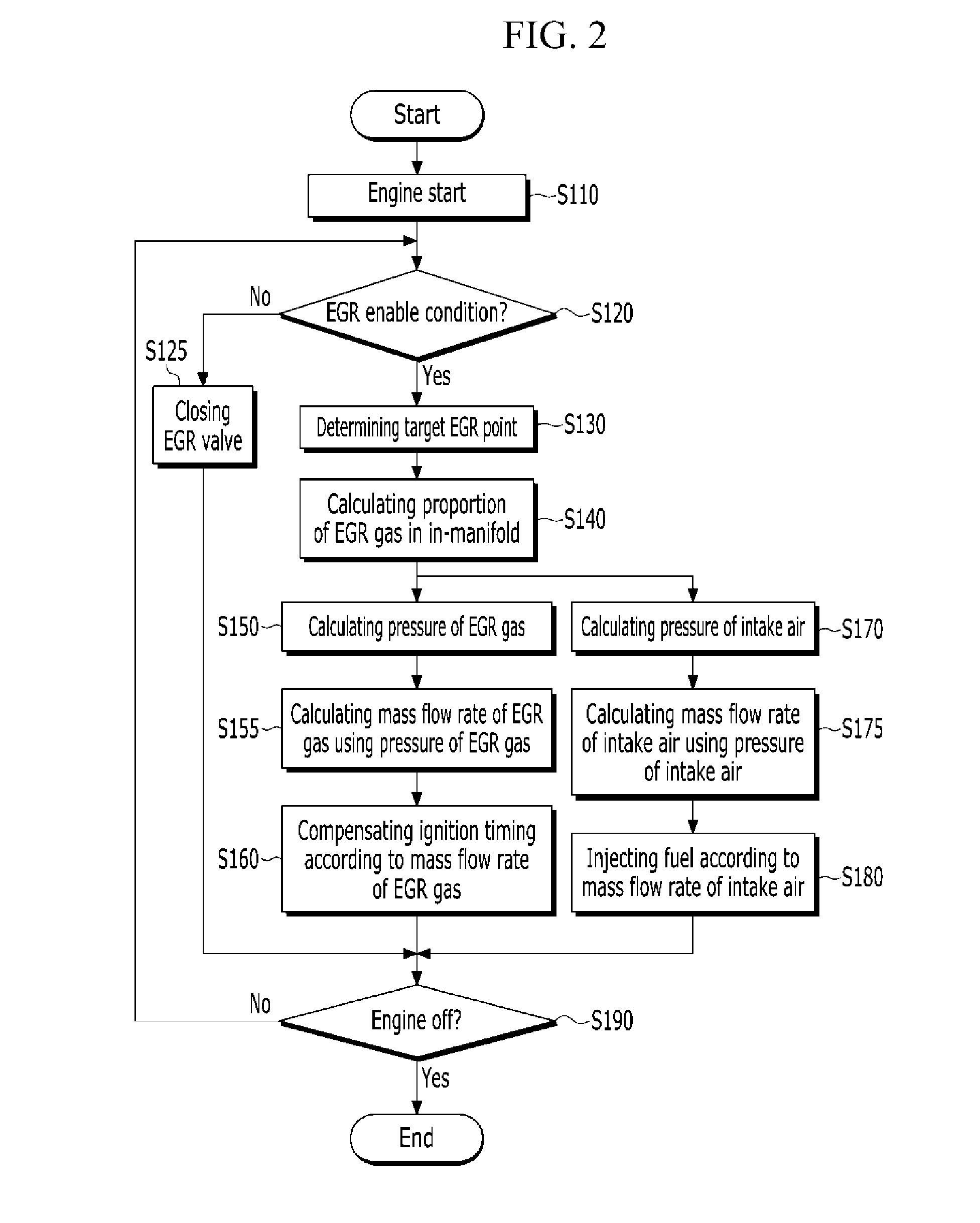
The present invention provides an exhaust gas recirculation control system that can calculate how much engine exhaust gas has been returned back into the air intake without relying on many sensor inputs. This allows for better control over this important process with minimal effort.

Problems solved by technology

The technical problem addressed in this patent relates to finding ways to reduce harmful emissions from engines, particularly nitrogen oxides (NOx), which can cause health issues if released into the atmosphere. One way to achieve this reduction is through the use of exhaust gas recirculation (EGR), which involves adding some of the engine's exhaust gas back into the cylinders during operation. However, accurate measurement of the amount of EGR gas being recirculated has been difficult because current methods require expensive sensors or result in complicated engine configurations. This patent seeks to address these challenges by providing a new approach for measuring EGR gas levels more efficiently and effectively.

Method used


Image

  • Apparatus and method for controlling exhaust gas recirculation
  • Apparatus and method for controlling exhaust gas recirculation
  • Apparatus and method for controlling exhaust gas recirculation

Examples


Embodiment Construction

[0032]Reference will now be made in detail to various embodiments of the present invention(s), examples of which are illustrated in the accompanying drawings and described below. While the invention(s) will be described in conjunction with exemplary embodiments, it will be understood that present description is not intended to limit the invention(s) to those exemplary embodiments. On the contrary, the invention(s) is / are intended to cover not only the exemplary embodiments, but also various alternatives, modifications, equivalents and other embodiments, which may be included within the spirit and scope of the invention as defined by the appended claims.

[0033]Like reference numerals designate like elements throughout the specification.

[0034]Throughout this specification and the claims that follow, when it is described that an element is “coupled” to another element, the element may be “directly coupled” to the other element or “electrically coupled” to the other element through a thi...


PUM


Abstract

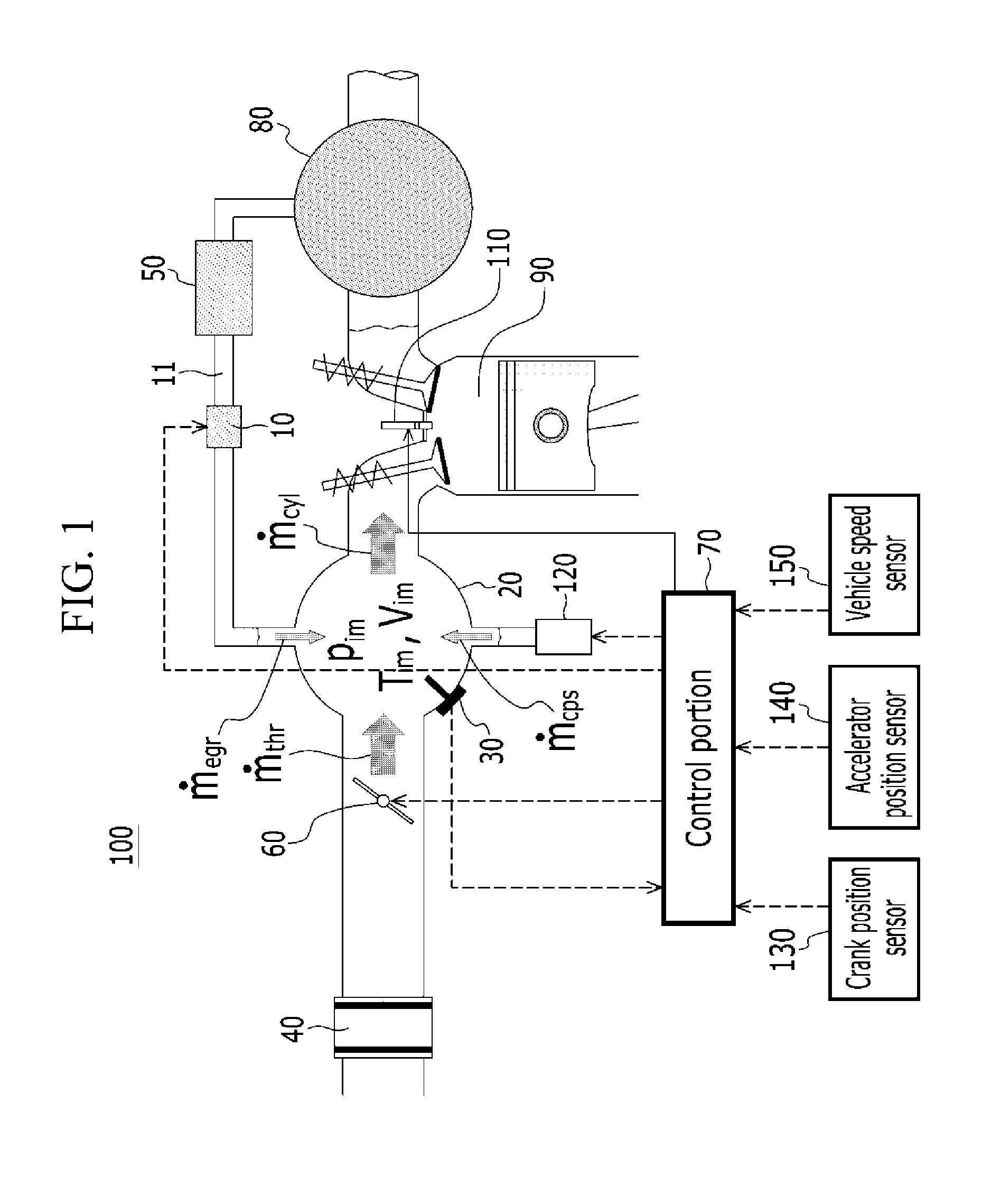
An exhaust gas recirculation control apparatus includes: an EGR valve adjusting a flow rate of EGR gas recirculated from an exhaust manifold to an intake manifold; a manifold absolute pressure (MAP) sensor measuring pressure inside the intake manifold; a throttle valve controlling the amount of inflow air; an igniter spraying fuel; an acceleration pedal angular position sensor; a crank position sensor measuring engine RPM; a vehicle speed sensor measuring a speed of a vehicle; and a control portion receiving a pressure signal from the MAP sensor, calculating a ratio of the EGR gas for a total volume of the intake manifold by using pressure variance inside the intake manifold, calculating pressure of the EGR gas by multiplying the pressure of the intake manifold and the ratio of the EGR gas, and converting the pressure of the EGR gas to a flow rate of the EGR gas.

Description


Claims


Application Information

Patent Timeline
Owner HYUNDAI MOTOR CO LTD
Why Eureka
Try Eureka