Dust extraction system for a power tool

a technology of dust extraction system and power tool, which is applied in the field of power tools, can solve the problems of dust affecting the use and affecting the user's ability to grasp the tool, etc., and achieves the effect of reducing the profile and weight, facilitating and quickly mounting and removing, and not affecting the maneuverability of the power tool

Active Publication Date: 2013-10-03
ROBERT BOSCH TOOL +1
View PDF2 Cites 4 Cited by
  • Summary
  • Abstract
  • Description
  • Claims
  • Application Information

AI Technical Summary

Benefits of technology

[0012]The dust extraction system can be easily and quickly mounted and removed from a hand-held power tool. The system has a minimal profile and weight so that it does not interfere with the maneuverability of the power tool or interfere with the user's ability to grasp the tool. Since the collet nut is integrated with the impeller the dust extraction system does not increase the overall length of the tool. The system may also be modified to incorporate other accessories, such as a depth guide.

Problems solved by technology

Hand-held power tools are known to generate a substantial amount of dust while cutting.
Such dust may interfere with further cutting by accumulating on the surface of the workpiece, on the tool bit, and / or within the cutting tool itself.
This may be particularly undesirable if the hand-held power tool is being used in a “clean” environment, such as within a finished room (e.g., decorated, furnished, carpeted, etc.) since additional cleanup may be necessary.
Further, requiring a hand-held power tool to be coupled to a standalone vacuum system often makes use of the hand-held power tool more cumbersome.
For example, the vacuum conduit coupling the adapter to the standalone vacuum system may interfere with the mobility or range of use of the tool.
Further, the vacuum conduit may disrupt the balance or feel of the tool for a user.
Such vacuum systems increase the overall size and weight of the power tools.

Method used


Image

  • Dust extraction system for a power tool
  • Dust extraction system for a power tool
  • Dust extraction system for a power tool

Examples


Embodiment Construction

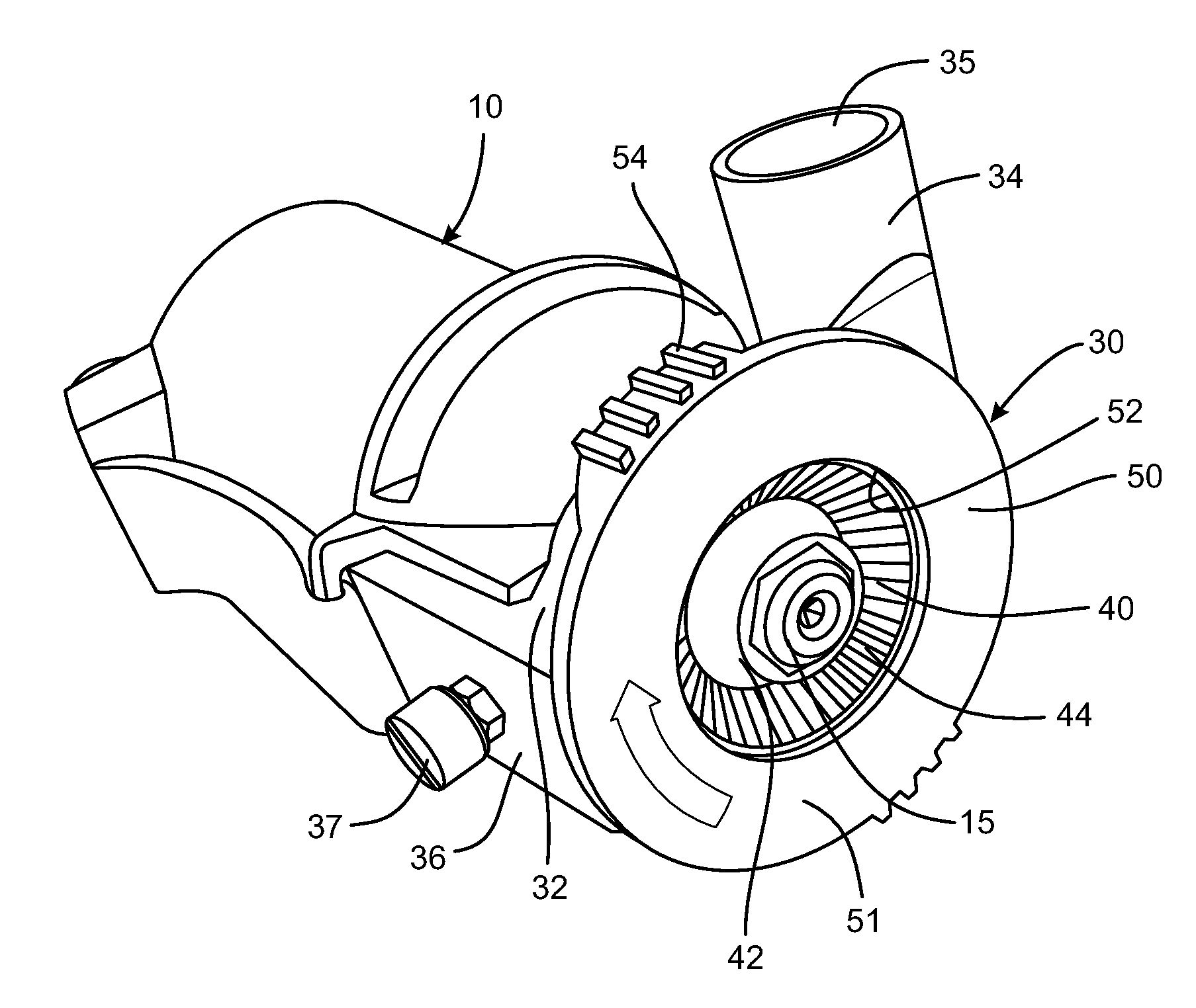
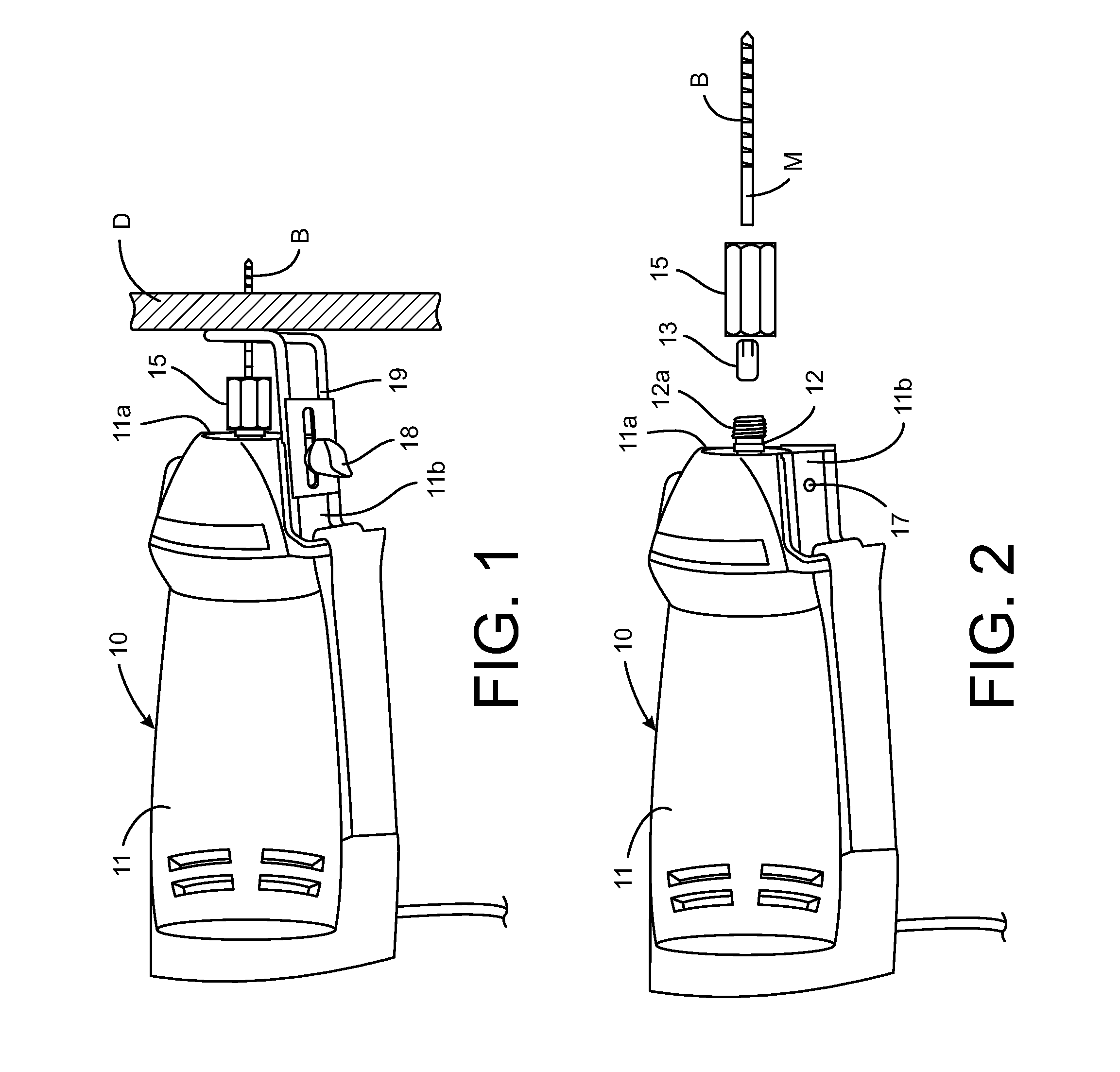
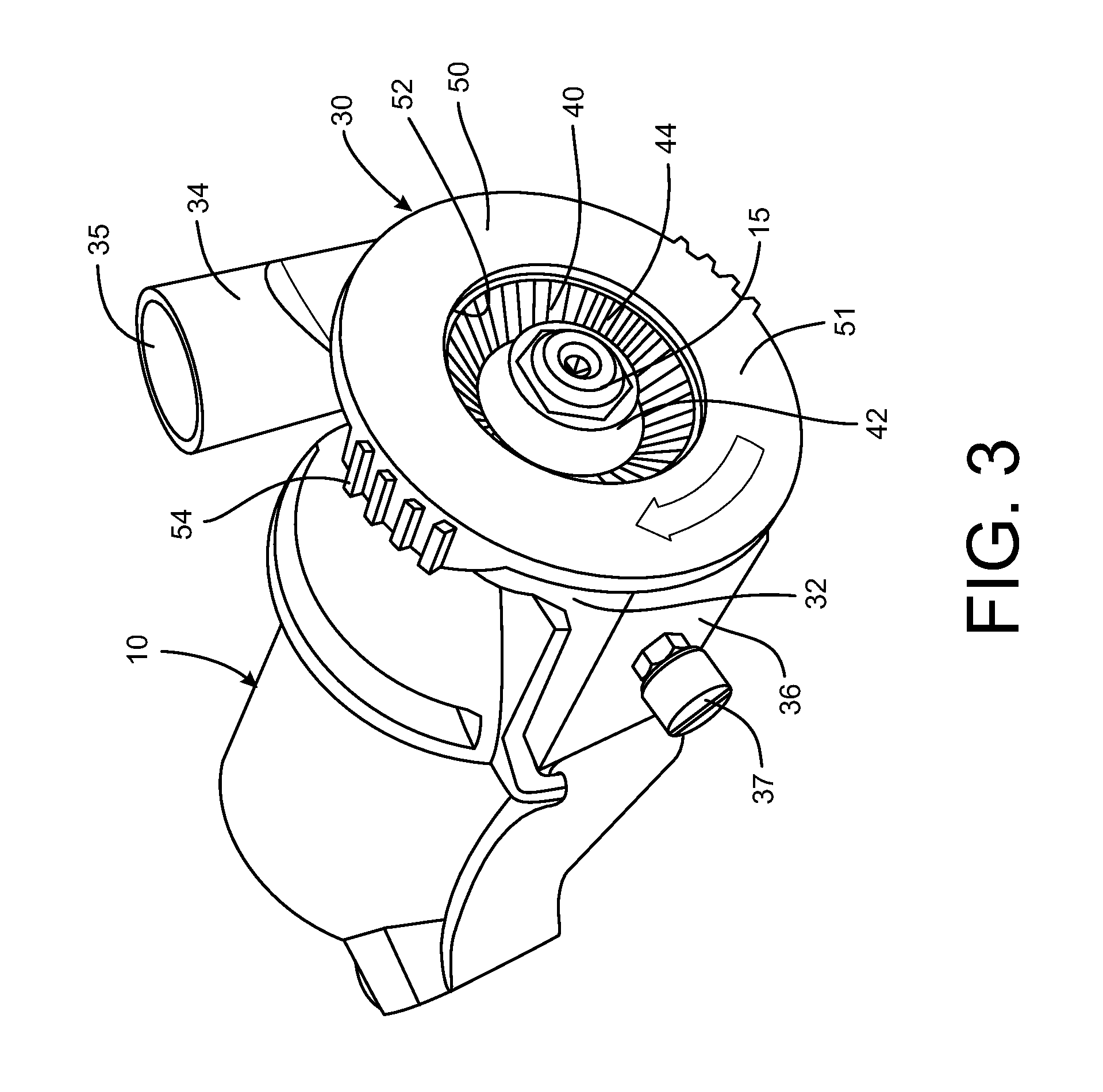
[0026]Referring to FIGS. 3-4, a dust extraction system 30 is shown engaged to the power tool 10. It is understood that the particular power tool is for illustrative purposes only and that the system 30 may be modified for engagement to a variety of power tools having an output shaft 12 and tool engaging collet arrangement. The dust extraction apparatus 30 includes a base 32 that is configured to seat onto the working end 11a (FIG. 1) of the tool housing 11. As shown in FIG. 4, the base may incorporate a mounting plate 36 that is configured to seat on the surface 11b of the tool housing. A mounting bolt 37 may extend through a collar 36a on the mounting plate and into the threaded bore 17 (FIG. 2) of the tool housing surface 11b. It is contemplated that the system base may be configured to accommodate other accessory mounting features for a particular power tool. Alternatively, the base 32 may include other features or elements to clamp onto the working end 11a of the tool housing 11...


PUM


Abstract

A dust extraction system for a power tool having a output shaft, a collet configured for engaging a tool bit and a collet nut engageable to the output shaft, comprises a base configured for mounting on the power tool, the base defining a cavity having an opening for passage of the output shaft therethrough and a discharge chute in communication with the cavity. The system further includes an impeller sized and configured to be rotatably received within the cavity, including a hub and a plurality of vanes emanating from the hub configured to draw dust from the workpiece into the cavity and to direct the dust through the discharge chute. A collet nut is integrated into the hub of the impeller so that the impeller can be directly mounted to the output shaft of the power tool while clamping the collet onto the tool bit.

Description

BACKGROUND[0001]The present disclosure relates generally to the field of power tools. More specifically, the present disclosure relates to power tools that include systems for collecting or otherwise removing debris (e.g., particles, dust, sawdust, chips, etc.) generated during operation of the power tools.[0002]Power tools generally include a housing and a motor contained within or at least partially enclosed by the housing. The motor is configured to move a tool bit or other accessory at high speeds to penetrate materials such as wood, drywall, tile, stone, etc. For example, a rotary cutting tool 10 such as that shown in FIGS. 1-2 includes a hand-held motor housing 11 with the motor output shaft 12 projecting from the working end 11a of the tool. A collet 13 supports a cutting bit B and is locked to the output shaft by a collet nut 15 that is internally threaded to engage the external threads 12a of the output shaft. The collet 13 and collet nut 15 cooperate so that the collet cla...

Claims


Application Information

Patent Timeline
Patent Type & Authority Applications(United States)
IPC IPC(8): B23Q11/00
CPCB23Q11/0046
Inventor RUBENS, JEREMYMORENO, JAIMEMARTINEZ, CHASTITY
Owner ROBERT BOSCH TOOL
Why Eureka
Try Eureka